
- Catalogs
- Yaskawa America, Inc. - Drives & Motion Division
- Large Capacity Sigma-5 Series Product Catalog


Large Capacity Sigma-5 Series Product Catalog

Large Capacity Sigma-5 Series Product Catalog
The document is a catalog for the SGDV series of large-capacity AC Servo Drives, including servomotors, SERVOPACKs, and converters. The series is ISO9001 and ISO14001 certified, ensuring quality and environmental management.
The catalog provides specifications for 200V and 400V class models with power capacities from 22kW to 55kW. It details servomotor and SERVOPACK designations, power supply voltage, current, and interface types.
Servomotors are available in flange-mounted and foot-mounted types, with options for holding brakes and oil seals. Specifications include rated outputs, speeds, torques, and current ratings, along with mechanical structure details like allowable radial and thrust loads.
Guidelines emphasize proper environmental conditions, such as temperature and humidity, for optimal performance. Servomotors should be used in well-ventilated, dust-free environments, with specific mounting instructions.
Includes torque-motor speed characteristics, continuous and intermittent duty zones, overload characteristics, and maintaining effective torque within specified limits.
Information on peripheral devices like noise filters, regenerative resistors, and dynamic brake units is provided, along with cable selection and system configuration for optimal performance.
Products comply with international standards, and warranty information is included to ensure customer satisfaction and product reliability.
- I/O Signal: Encoder output pulses with line driver output for phases A, B, and C. Sequence input includes 7 channels for various functions, and sequence output includes 3 channels for functions like positioning completion.
- MECHATROLINK Communications: Supports MECHATROLINK-II and III protocols with specified transmission speeds and cycles.
- Power Supply Capacities and Power Losses: Detailed tables provide power supply capacities, output currents, and power losses for different SERVOPACK models.
- Operating Conditions: Ambient temperature range is 0 to +55˚C, with storage conditions from −20 to +85˚C. Humidity should be 90%RH or less without freezing or condensation.
- Protection and Safety: Includes overcurrent, overvoltage, and overload protection, complying with standards like EN954 category 3 and IEC61508 SIL2.
- Mounting and Dimensions: Provides detailed dimensional drawings and mounting hole diagrams for various SERVOPACK models.
- Control Method: IGBT PWM control with sine-wave driven feedback. Speed control range is 1:5000 with specific speed regulation tolerances.
- Communications Interface: RS-422A and USB interfaces for digital operators and personal computers, supporting SigmaWin+ software.
- Ensure operating conditions are met to avoid damage or malfunction.
- Use recommended external components like dynamic brake units and regenerative resistors for optimal performance.
- Perform risk assessments to confirm safety requirements are fulfilled before using specific functions.
Specifications for holding brake power supply units include models LPSE-2H01-E for 200 V input and LPDE-1H01-E for 100 V input, with a rated output voltage of 90 VDC and a maximum output current of 1.0 A.
Switch the holding brake’s power supply on the AC side to reduce brake operation time. Install a surge absorber when switching on the DC side to prevent damage from surge voltage.
Select appropriate surge absorbers and diodes based on the power voltage and current of the brake. Surge absorbers do not have polarity, while diodes do.
Regenerative resistors absorb regenerative power from servomotors. Guidelines for using Yaskawa and other manufacturers' resistors are provided, emphasizing avoiding negative load operations.
Standards for regenerative resistors and dynamic brake units include required clearances for cooling and external dimensions for various models.
Dynamic brake units process dynamic braking energy. Selection criteria and specifications for Yaskawa models and recommendations for other manufacturers are provided.
- Using a Dynamic Brake Unit from Yaskawa: Integrated dynamic brake contactor with specific parameter settings in the SERVOPACK.
- Using a Dynamic Brake Unit from Another Company: Requires an NO relay and power supply for NC contactors with coil current ≥ 300 mA.
- Speed Control: Use SigmaJunmaSize+ for capacity selection, considering load speed, gear ratio, and mechanical efficiency.
- Position Control: Focus on positioning accuracy and torque requirements, ensuring servomotor specifications and verification steps are met.
- Allowable Frequency Calculation: Based on servomotor and load inertia.
- Regenerative Energy Calculation: Includes calculating rotational energy, load loss energy, and energy absorbed by the SERVOPACK.
Diagrams illustrate the relationship between input power supply voltage and absorbable energy for different SERVOPACK and converter models.
Diagrams show the relationship between generated torque and winding resistance loss for various SGMVV servomotor models.
The SERVOPACK SGDV series complies with UL Standards, CE Mark, KC Mark, RoHS Directives, and Safety Standards. The SGMVV servomotors comply with UL Standards, CE Mark, and RoHS Directives.
Yaskawa America, Inc. provides contact details for their Drives & Motion Division, emphasizing their commitment to customer service and quality.
Yaskawa emphasizes a personal commitment to customer satisfaction, highlighting their dedication to training, customer treatment, and product quality.
Catalog excerpts

QUALITY SYSTEM AC Servo Drives Large Capacity Series Product Catalog ENVIRONMENTAL SYSTEM
Open the catalog to page 1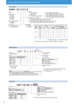
Series Model Designation SGMVV - 2 B A D B 2 N Options N : Without options 1 : With dust seal S : With oil seal B : With holding brake (90 VDC) : With holding brake (24 VDC) : With holding brake (90 VDC) and oil seal : With holding brake (24 VDC) and oil seal : With holding brake (90 VDC) and dust seal : With holding brake (24 VDC) and dust seal Main Mechanical Structure 2 : Flange type, straight shaft end without key and no tap 6 : Flange type, straight shaft end with key and tap K : Foot-mounted type, straight shaft end without key and no tap L : Foot-mounted type, straight shaft end with key...
Open the catalog to page 2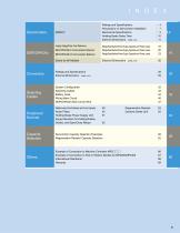
MECHATROLINK-III Communications Reference Ratings/Specifications/Power Supply Capacities and Power Losses Ratings/Specifications/Power Supply Capacities and Power Losses Ratings/Specifications/Power Supply Capacities and Power Losses Ratings and Specifications Precautions on Servomotor Installation Mechanical Specifications Holding Brake Delay Time External Dimensions Units: mm External Dimensions Units: mm Analog Voltage/Pulse Train Reference MECHATROLINK-II Communications Reference Ratings and Specifications External Dimensions Units: mm Selecting Cables System Configuration Selecting Cables...
Open the catalog to page 3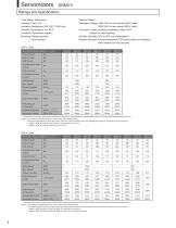
Ratings and Specifications Thermal Class: F Withstand Voltage: 1500 VAC for one minute (200-V class) 1800 VAC for one minute (400-V class) Enclosure: otally enclosed, separately cooled, IP44 T (except for shaft opening) Ambient Humidity: 20% to 80% (no condensation) Rotation Direction: Counterclockwise (CCW) with forward run reference when viewed from the load side Time Rating: Continuous Vibration Class: V15 Insulation Resistance: 500 VDC, 10 MΩ min. Ambient Temperature: 0 to 40˚C Excitation: Permanent magnet Mounting: Flange-mounted Foot-mounted 200-V Class Servomotor Model: SGMVVRated Output*...
Open the catalog to page 4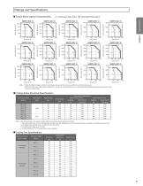
: Intermittent Duty Zone : Continuous Duty Zone Notes: 1 When the effective torque is within the rated torque, the servomotor can be used within the intermittent duty zone. 2 hen the main circuit cable length exceeds 20 m, note that the intermittent duty zone of the Torque-Motor Speed Characteristics will shrink as the W line-to-line voltage drops. 1Holding Brake Electrical Specifications Servomotor Model Rated Speed Rated Output Holding Brake Specifications Rated Voltage 24 VDC Rated Current Rated Current Notes: 1 The holding brake is only used to hold the load and cannot be used to stop the...
Open the catalog to page 5
Ratings and Specifications 1Overload Characteristics The overload detection level is set under hot start conditions at a servomotor ambient temperature of 40° C. Motors with Rated Speed of 1,500 RPM Motors with Rated Speed of 800 RPM 120 140 160 180 200 220 Torque reference (percent of rated torque) (%) 120 140 160 180 200 Torque reference (percent of rated torque) (%) Note: verload characteristics shown above do not guarantee continuous duty of 100% or more output. O Use a servomotor with effective torque within the continuous duty zone of Torque-Motor Speed Characteristics . 1Allowable Load...
Open the catalog to page 6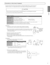
Precautions on Servomotor Installation The service life of the servomotor will be shortened or unexpected problems will occur if the servomotor is installed incorrectly or in an inappropriate location. Always observe the following installation instructions. CAUTION • o not connect the servomotor directly to a commercial power line. This will damage the servomotor. D The servomotor cannot operate without the proper SERVOPACK. (1) Installation Environment Items Ambient Temperature Ambient Humidity Installation Site •Free of corrosive or explosive gases. •Well-ventilated and free of dust and moisture....
Open the catalog to page 7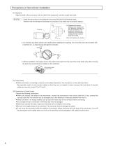
Precautions on Servomotor Installation (4) Alignment Align the shaft of the servomotor with the shaft of the equipment, and then couple the shafts. 1 Install the servomotor so that alignment accuracy falls within the following range. Vibration that will damage the bearings and encoders if the shafts are not properly aligned. Alignment Accuracy *: Measure this distance at four different positions on the circumference. The difference between the maximum and minimum measurements must be 0.03 mm or less. Note: Turn together with coupling. 2 o not allow any direct impact to the shafts when installing...
Open the catalog to page 8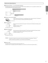
Mechanical Specifications 1Mechanical Tolerance T.I.R. (Total lndicator Reading) Servomotors The following figure shows tolerances for the servomotor’ output shaft and installation area. For more details on tolerances, refer s to the external dimensions of the individual servomotor. Perpendicularity between the flange face and output shaft (flange-mounted servomotors only) 0.05 A Run-out at the end of the shaft 0.03 Mating concentricity of the flange O.D. (flange-mounted servomotors only) 0.05 Dia. A 1Direction of Servomotor Rotation Positive rotation of the servomotor is counterclockwise when...
Open the catalog to page 9
Holding Brake Delay Time Holding brakes have motion delay time that varies depending on when the brake is open and when the brake is operating. The following table shows the brake delay time of each servomotor. Make sure the holding brake delay time is correct for your servomotor. 3Example, switching the holding brakes on the DC side Main Circuit Power Servomotor Model Rated Speed Supply Voltage Brake Open Time Brake Operation Time 4ED D * : An SGMVV-4ED D servomotor is not available in a model with a holding brake.
Open the catalog to page 10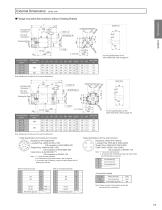
External Dimensions Fan-end Connector Encoder-end Connector 1Flange-mounted Servomotors without Holding Brakes For the specifications of the other shaft ends, refer to page 19. Approx. Mass kg Note: Models with oil seals are of the same configuration. For the specifications of the other shaft ends, refer to page 19. Servomotor Model SGMVV- Fan-end Connector Encoder-end Connector Note: Models with oil seals are of the same configuration. • Cable Specifications for Encoder-end Connector M A B N L C P T K D S R J E H F G •Cable Specifications for Fan-end Connector Receptacle: 97F3102E20-29P L-shaped...
Open the catalog to page 11All Yaskawa America, Inc. - Drives & Motion Division catalogs and technical brochures
 U1000
U100017 Pages
 MV1000NEMA 3R
5 Pages
 MV1000
13 Pages
 SG400
SG4002 Pages
 GP7 AND GP8
2 Pages
 INTEGRATED SOLUTIONS
11 Pages
 SIGMA TRAC II
9 Pages
 R1000
R100011 Pages
 iQPUMP AC DRIVE
13 Pages
 FP605
FP60515 Pages
 iQrise
2 Pages
 HV600
HV60019 Pages
 MACHINE CONTROL PRODUCTS
21 Pages
 D1000
D10002 Pages
 GA500
GA5009 Pages
 AC DRIVE SOFTWARE TOOLS
8 Pages
 YASKAWA AC Drive-L1000A
524 Pages
 1000 Series Low Voltage
15 Pages
 Yaskawa IEC Robot Control
5 Pages
 Yaskawa Type 3R Package
6 Pages
 Sigma SD
60 Pages
 GA800
GA8002 Pages
 MicroMax Marathon AC Motors
2 Pages
 L1000A
2 Pages
 BlackMax Marathon AC Motors
2 Pages
 BlueMax Marathon AC Motors
4 Pages
 NEMA Premium Efficiency XRI
2 Pages
 Yaskawa AC Drives PLC
2 Pages
 Deming Award
2 Pages
 SigmaLogic7 Compact
2 Pages
 Single Phase Converter
2 Pages
 Sigma-7 Servo Systems
4 Pages
 Z1000 Family of Drives Catalog
28 Pages
 iQpump Family Catalog
20 Pages
 Z1000 Bypass
2 Pages
 Z1000 Drive, 3HP to 500HP
2 Pages
 IEC - Comm Toolbox
2 Pages
 MP3200iec
2 Pages
 P1000 Catalog
52 Pages
 SGMMV
SGMMV20 Pages
 Bestact
64 Pages
 Sigma II Servo Catalog
202 Pages
 Sigma-5 Series Product Catalog
357 Pages
 A1000 Catalog
58 Pages
 YASNAC 3000G
203 Pages
 LEGEND-MC (SMC-3010)
2 Pages
 YASNAG 2000G
58 Pages
 variable frequency drives
7 Pages
 Sigma-5 Servo Family
8 Pages
 Junma Series Servo
12 Pages


Archived catalogs
 Flyer Yaskawa Factory Repair
2 Pages


- Electromotor
- Synchronous motor
- Industrial robot
- Alternating current motor
- Electric gearmotor
- Automation software solution
- Digital I/O
- Proximity switch
- Electromotor for industrial applications
- Three-phase motor
- Real-time software
- Articulated robot
- Windows software
- IO module
- 6-axis robot
- Switching relay
- Analog I/O
- Digital IO module
- Handling robot