
Catalog excerpts
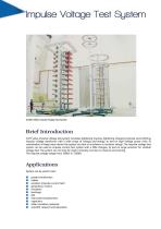
Brief Introduction CJDY series impulse voltage test system simulates lightening impulse, lightening chopping impulse and switching impulse voltage waveforms with a wide range of voltage and energy, to test on high voltage power units. In coordination of steep wave device the system can test on insulators or insulator strings. The impulse voltage test system can be used as impulse current test system with a little changes, to test on surge arrestors for residual voltage test. The system can not only be used in industry, but also in research and training. The impulse voltage ranges from lOOkV...
Open the catalog to page 2
rB Low inductance of the whole circuit B easy and fast change of configuration, to satisfy various of testing requirements B computer-aided control system, user friendly operation interface B excellent safety protection device B can be used in combination with AC or DC test system System is composed by impulse voltage generator, charging unit, damping voltage divider, chopping device, steep wave device, control and measurement system, wave-shaping units and isolating impedance. The impulse voltage generator is parallel charged through the charging unit. Trigger the ignition device, and...
Open the catalog to page 3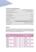
Technical Specifications Waveforms : Standard lighting impulse : Standard switching impulse : Front time of lighting impulse wave <15pS Min output voltage: Charging voltage instability: Synchronization range: Synchronous discharge malfunction: Ignition range: Running time: Efficiency of generator: Chopping time: discontinuous running (charge and discharge every 300s) when >70%Un, continuous running (charge and discharge every 120s) when <70% Un lightening wave (no-load) >90 % CJDY-E Type E generator uses single insulating tube to prop the generator, suspended with two single-bushing...
Open the catalog to page 4
CJDY-G Type G generator uses insulating tube to prop double-bushing capacitors. Stage voltage is lOOkV. The generator is composed by capacitors, front-wave and tail-wave resistors and discharge gaps. All wave-shaping units are built-in, while the discharge gaps are exposed. The generator and charging unit are fixed on separate moveable bases.. Type G generator is suitable for relative low voltage and low capacity loading objects.
Open the catalog to page 5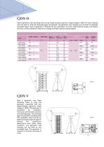
CJDY-D Type D generator uses insulating tube to prop single-bushing capacitors. Stage voltage is lOOkV. All wave-shaping units are built-in, while the discharge gaps are exposed. The generator and charging unit are fixed on separate moveable bases. Type D generator is featured by low inductance of circuit, large impulse energy, and impact structure, mostly suitable for relative low voltage and high capacity loading objects. Voltage Stage No. Stage voltage Stage Type V generator uses three insulating tubes to prop the generator, suspended with two single-bushing capacitors. Stage voltage is...
Open the catalog to page 6
CJDY-H Type H generator uses four insulating tubes to prop the generator, suspended with two single-bushing capacitors. Bilateral symmetrical charging is used, charging voltage is ±100kV. The discharge gaps are housed in insulating tube with ventilation. Clean and dry air keeps flowing through the gaps to improve the synchronous performance even under heavy conditions. Each three stages is equipped with an insulating platform. At each stage there is a bracket for placing wave-shaping units. The generator and charging unit are fixed on one moveable base. The system is equipped with steel...
Open the catalog to page 7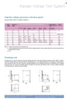
* means for transformer inner insulation only For high voltage power cable, here we refer to thermal voltage withstand. Impulse voltage withstand for power cable should not exceed the max in the list, in k V Charging unit Charging unit is used to charge the impulse voltage generator. Typically charging voltage is either lOOkV or 200kV. The unit is either fixed on the same base for the generator or on a separate base. It is connected to the generator with conductive tube. The unit consists of voltage regulation unit, charging transformer, rectification unit, voltage measurement unit, remote...
Open the catalog to page 9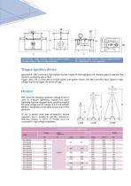
Oil-immersed double bushings; 1366(L)X1166(W)X1250(H) ; Oil-immersed single bushing; 1700(L)X1250(W)X1900(H) ; charging voltage: ±100kV; for type H generator DC voltage:200kV; for type V generator Trigger ignition device generates 8~15kV continuous high voltage impulse. Trigger of discharge gaps and chopping gaps is separate. The control is isolated by optical fiber. Trigger delay unit is connected to control system and ignition device. The latter transfers input signals to high voltage impulse to trigger the sphere air gap. Divider DDF series low damping capacitive voltage divider...
Open the catalog to page 10
Chopping device chops lightening impulse front wave or tail wave. Gap distance is adjusted via motor controlled by operation device. Trigger signals are isolated by optical fiber. Delay is realized by hardware together with software. y Resistive Voltage Divider Resistive voltage divider takes advantage of small dimension and low impedance in order to get fast response. The divider is oil-immersed. Same as steep wave sphere gap, the resistive voltage divider is also fixed on moveable base. Partial response Stabilizing Overshoot Uncertainty in time time dividing ratio
Open the catalog to page 11
lExFJ DB-Series Steep Wave Test Device Shunt Shunt is used in injury current measurement of transformer. It consists of metal column with flanges. Shunt has a simple structure. The inner core is easy to change. Resistance of the core is 0.10,0.20,0.50 or 10. Dimension of shunt: 290mm(L)x73mm(H)x45mm(D)x70mm(W) Type G generator uses insulating tube to prop double-bushing capacitors. Stage voltage is lOOkV. The generator is composed by capacitors, front-wave and tail-wave resistors and discharge gaps. All wave-shaping units are built-in, while the discharge gaps are exposed. The generator and...
Open the catalog to page 12
C. Over shoot compensation If capacitance of test object is very large, front-wave resistance shall go down, and then parasitic inductance of the discharge circuit cannot be neglected any more. Resonance will happen between the inductance and capacitance. Then surge occurs at the front wave, peak over shoot is over 5%. In this case additional compensation is needed between the generator and test object. Choose suitable Cd, Ld and Rd. Working principle as below:
Open the catalog to page 13All YangZhou Xinyuan Electric Co. catalogs and technical brochures
-
Voltage Regulator
4 Pages
-
Heat Cycling Test System
8 Pages
-
DC High Voltage Test System
12 Pages
-
Cable Termination System
4 Pages
-
AC Test Transformer
12 Pages
-
AC Resonant Test System
8 Pages
-
PowerHV- Project photos
79 Pages


