- Catalogs
- Yamaha Motor Co.,Ltd.
- GF series
- Company
- Products
- Catalogs
- News & Trends
- Exhibitions
GF series
1 /2Pages

GF series
1 /2Pages
Catalog excerpts
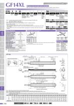
Model S: Straight model Installation direction H: Horizontal installation Lead designation Single-axis robots Origin on the non-motor side is selectable Note. If you need an installation posture other than the horizontal installation, please contact us. TSX Cable entry location No entry: Standard (S) U: From the top R: From the right L: From the left Origin position change None: Standard Z: Nonmotor side Frame No entry: Standard (Spot facing) T: Tapping Grease type None: Standard GC: Clean Driver: Power-supply voltage / LCD Power capacity monitor 110: 100V/200W No entry: None 210: 200V/200W L: With LCD Robonity TRANSERVO Motor-less single axis actuator Note 1. The robot cable is standard cable (3L/5L/10L), but can be changed to flexible cable. See P.732 for details on robot cable. Note 2. See P.634 for DIN rail mounting bracket. Note 3. Select this selection when using the gateway function. For details, see P.96. Compact single-axis robots [Cautions after purchase] • When changing the origin position, contact us since the adjustment is needed. • When changing the cable entry location, contact us since necessary parts may vary depending on the cable entry location. • Do not install the robot with the horizontal installation specifications in a direction other than the horizontal direction. RDV-X Driver Cartesian robots Maximum payload (kg) Rated thrust (N) Stroke (mm) Overall length (mm) Stroke+561 Maximum dimensions of cross W140×H91.5 section of main unit (mm) Cable length (m) Standard: 3.5 / Option: 5,10 Linear guide type 4 rows of circular arc grooves × 2 rail Position detector Resolvers Note 2 Resolution (Pulse/rotation) 20480 Battery B: With battery (Absolute) N: None (Incremental) Regenerative unit Static loading moment MY I/O selection N: NPN P: PNP CC: CC-Link DN: DeviceNetTM PB: PROFIBUS SCARA robots Controller Operation method Programming / SR1-X10 I/O point trace / RCX320 Remote command / RCX221/222 Operation using RS-232C RCX340 communication TS-X110 I/O point trace/ Remote command TS-X210 RDV-X220-RBR1 Pulse train control Note. istance from center of slider top to center of gravity of object being carried at a guide service D life of 10,000 km. Note. Service life is calculated for 1000mm stroke models. Note 1. Positioning repeatability in one direction. Note 2. Position detectors (resolvers) are common to incremental and absolute specifications. If the controller has a backup function then it will be absolute specifications. Pick & place robots Direction of robot cable extraction Approx. 250 346+/-3: (Motor cable length) When origin is on motor side (346: When origin is on non-motor side) 140 Cable securing 128 263+/-1 (Note 1) position (Note 3) 70 (215:When origin is on motor side) 215+/-3: When origin is on non-motor side 132+/-1 Effective stroke Linear motor single-axis robots Ball screw lead (mm) Maximum speed (mm/sec) Battery B: With battery (Absolute) N: None (Incremental) Power-supply voltage Driver: Power capacity 2: AC200V 20: 600W or less Single-axis robots I/O selection NP: NPN PN: PNP CC: CC-Link DN: DeviceNetTM EP: EtherNet/IPTM PT: PROFINET GW: No I/O board Note 3 10 Driver: Power capacity Usable for CE 10: 200W No entry: Standard E: CE marking Allowable overhang Note Specifications AC servo motor output (W) Repeatability Note 1 (mm) Deceleration mechanism Linear conveyor modules Ordering method Articulated robots ϕ10 H7 Depth 11 (See cross-section A-A.) A Spot facing hole installation specifications ϕ10 H7 Depth 11 (See cross-section A-A.) A Tapping hole installation specifications 4-M5x0.8 Depth 11 (The same position on the opposite surface at 2 locations) CONTROLLER INFORMATION Note 1. Stop positions are determined by the mechanical stoppers at both ends. Details of D Note 2. When changing the return-to-origin direction, the adjustment is needed. (The standard is the origin on the motor side.) Note 3. Secure the cable with a tie-band 100mm or less from unit’s end face to prevent the cable from being subjected to excessive loads. Note 4. The cable’s minimum bend radius is R30. Note 5. The length under head of the hexagonal socket head bolts (M6 x 1.0) that are used to install the main body with the spot facing hole installation specifications is 20mm or more. It is recommended that the length under head of the hexagonal socket head bolts (M6 x 1.0) that are used to install the main body with the tapping hole installation specifications is the thickness of the installation base + 10mm or less. Effective stroke L A B C Weight (kg)
Open the catalog to page 1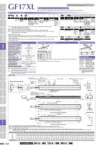
Origin on the non-motor side is selectable Note. If you need an installation posture other than the horizontal installation, please contact us. Cable entry Installation Lead location direction designation H: Horizontal No entry: installation Standard (S) U: From the top R: From the right L: From the left Frame Stroke Grease type 850 to 2500 No entry: Standard None: Standard (50mm pitch) (Spot facing) GC: Clean T: Tapping Origin position change None: Standard Z: Nonmotor side RBR1 Static loading moment Linear motor single-axis robots Cartesian robots Ball screw lead (mm) 20 Maximum speed (mm/sec)...
Open the catalog to page 2All Yamaha Motor Co.,Ltd. catalogs and technical brochures
 ROBOT CATLOG 2021-2022
771 Pages
 R series
3 Pages
 SS series
6 Pages
 LCMR200
27 Pages
 YRG-2005SS
2 Pages
 YAMAHA Vision System Ivy2
6 Pages
 NEW SCARA ROBOT : YK400XE
6 Pages
 YAMAHA SCARA LINEUP Catalogue
95 Pages
 YAMAHA SCARA No.1
2 Pages
 Lineup Catalog
14 Pages
 Infomation
32 Pages
 Electric grippers
14 Pages
 ROBOT VISION iVY2
13 Pages
 Clean robots
44 Pages
 Pick & place robots
10 Pages
 Controllers
132 Pages
 SCARA robots
67 Pages
 Cartesian robots
128 Pages
 Linear motor single axis robots
27 Pages
 Single axis robots
46 Pages
 Vertically articulated robots
14 Pages
 YAMAHA ROBOT Catalog 2018
627 Pages


Archived catalogs
 YAMAHA ROBOT CATALOG 2020/2021
673 Pages
- Cylinder
- Industrial robot
- Transport rail conveyor
- Linear actuator
- Belt conveyor
- Electric actuator
- Horizontal conveyor
- Positioning table
- 6-axis robot
- Conveyor for the food industry
- Floor-mounted robot
- Handling robot
- Motorized positioning table
- Compact actuator
- Electric drive conveyor
- Precision positioning table
- Compact robot
- Parallel gripper