
- Catalogs
- Yamaha Motor Co.,Ltd.
- Controllers

- Company
- Products
- Catalogs
- News & Trends
- Exhibitions
Controllers

Controllers
An optimal controller can be selected from various command input formats, allowing for quick operation of robots without complex settings due to pre-registered servo parameters and deceleration patterns.
The document lists various high-performance controllers supporting YAMAHA robots, including models like TS-S2, TS-SH, TS-X, TS-P, RCX221, RCX222, RCX240, RCX240S, RCX340, RDV-X, RDV-P, TS-SD, SR1-X, SR1-P, and ERCD. Each model supports different programming languages and command types, such as YAMAHA BASIC and SRC languages, and offers various functionalities like I/O point trace, remote command, and online command.
- Program Input: Supports a variety of operation settings, calculations, and conditional branching using YAMAHA SRC and BASIC languages.
- Easy Setup: Complicated parameter settings are unnecessary as optimal values for servo parameters are pre-registered.
- Multi-function and Expandability: Multi-axis controllers support up to 30,000 points and various field networks like CC-Link, DeviceNetTM, PROFIBUS, and EtherNet/IPTM.
- Dedicated Pulse Train Control: Offers compact design and cost reduction, with enhanced response frequency and reduced position setting time.
The document provides detailed specifications for each controller model, including the number of points, number of programs, applicable networks, and compliance with CE standards. It also highlights features like real-time operation status monitoring and easy replacement due to consistent parameter settings and fastening-hole pitches.
YAMAHA controllers offer a range of functionalities and ease of use, making them suitable for various robotic applications. Their design allows for quick setup and operation, with support for multiple axes and expandability through various network options.
The document outlines the features of a control system designed for easy positioning and enhanced interoperability with control devices. Key functionalities include remote commands for direct manipulation of numerical data, a gateway function to reduce network costs, and a unified design for clean installation. Supported network connections include CC-Link, EtherNet/IP™, and PROFINET.
The system features unified installation sizes for neat integration within control boards. It includes status indication lamps, communication connectors, and various I/O connectors. The absolute battery is easily replaceable from the front side, and DIN rail installation is standard on certain models.
The system allows easy positioning by specifying a registered point number and starting the operation. It supports various output functions linked with positioning operations, such as zone output, near position output, and pressing status. Jog and point teaching functions are standard, enabling simple teaching systems.
The gateway function allows unified management of up to four I/O interfaces, reducing network costs. Remote commands enable direct handling of data, promoting unified data management. Consecutive queries allow real-time updates of status information, useful for monitoring and interoperation with peripheral devices.
The system supports daisy-chain connections for managing up to 16 axes, with automatic device assignment for communication commands. The "KEYENCE PROTOCOL STUDIO Lite" software facilitates serial communication settings, supporting multiple languages. The system allows for multi-axis control and status monitoring without opening the control panel.
The document also describes torque limiting control, various command formats, and compact design improvements. It includes feedback pulse output functions, error history monitoring, and robot number management for simplified servo adjustments. The system supports multi-task functions and conditional stop functions during movement.
- Multi-task Support: Enhanced functionality for multi-tasking with improved operability and program input support for quick setup.
- Built-in Regenerative Unit: The regenerative unit is integrated, eliminating the need for additional units when connecting to existing robots.
- Programming Capacity: The RCX240 and RCX340 controllers have increased program and point capacities, with the RCX340 supporting up to 30,000 points.
- Language Support: The programming box supports Japanese, English, and Chinese, with a color display for better visibility.
- Data Management: Controller data can be saved to USB memory, facilitating easy data management and transfer.
- Includes emulator function and cycle time calculator.
- Supports various monitor panel layouts and data comparison tools.
- Facilitates easy function addition or editing, even for non-programmers.
- Supports centralized control of robots through connections of up to four RCX340 controllers.
- Standard RS-232C and Ethernet ports, with support for field buses like CC-Link, EtherNet/IP, DeviceNet, PROFIBUS, and PROFINET.
- YC-Link/E allows multiple robots to be managed as if operated by a single controller, reducing setup labor costs.
- Various controllers are detailed, including RCX240, RCX340, and others, with specifications on operating methods, input power, origin search methods, and field network support.
- Controllers support different robot types, including single-axis, Cartesian, SCARA, and pick & place robots.
- Details on electric grippers, linear conveyor modules, and other accessories are provided.
- Support software for PCs and programming boxes are listed with their respective functionalities.
The ERCD is a controller designed for single-axis robots, specifically the FLIP-X series models T4L, T5L, C4L, and C5L. It supports a DC24V motor with a capacity of 30W or less. The dimensions are W44 × H166 × D117mm, and it weighs 0.45kg. The input power supply is DC24V with a tolerance of +/-10%, and it can handle a current of 3A to 4.5A depending on the robot in use.
The drive method is an AC full-digital software servo with a resolver for position detection. It operates in normal mode with point trace movement and program operation, or in pulse train mode. Speed and acceleration settings range from 1% to 100%, with a resolution of 16384 P/rev. The origin search method is incremental.
The ERCD uses YAMAHA SRC programming language and supports multitasking with up to 4 tasks. It allows for manual data input, direct teaching, and remote teaching. The memory includes 32 Kbytes of RAM with lithium battery backup, supporting up to 100 programs and 1000 points.
In normal mode, it has 8 dedicated input points and 6 general input points, with 3 dedicated output points and 6 general output points. In pulse train mode, it has 5 dedicated input points. The command pulse input supports various types and modes, with a maximum frequency of 2 Mpps.
The ERCD should be installed inside a control panel on a vertical wall in a well-ventilated location. The ambient temperature should be between 0°C and 40°C, and humidity should be 35% to 85% RH.
Standard accessories include a 24V power connector and I/O cables. Optional support software for PC, POPCOM+, facilitates robot operation and programming. A programming box, HPB/HPB-D, is available for manual operations and program editing.
The operating temperature range is 0°C to 40°C, with storage temperatures from -10°C to 65°C. It has noise resistance capacity according to IEC61000-4-4 Level 2 and includes protective functions against overload, overvoltage, and other issues.
The ERCD supports RS-232C communication for external communications and includes various I/O connectors for sequence input and output, as well as pulse train input and output.
The document outlines the specifications for various robot controllers and motors. The maximum power consumption ranges from 400VA to 1400VA, with motor capacities from 100W to 600W. Dimensions and weights vary slightly between models, with the SR1-X and SR1-P models having specific dimensions and weights.
The control and motor power supplies are single-phase AC with voltage options of 100 to 115V or 200 to 230V, with a tolerance of +/-10% and frequency of 50/60Hz.
The drive method is an AC full-digital software servo, with position detection using a multi-turn resolver or magnetic linear scale. Operating methods include programming, I/O point tracing, remote command, and RS-232C communication.
The programming language used is YAMAHA SRC, supporting up to 4 multitasks and 100 programs with a total of 3000 steps. Point-data input can be manual or through direct teaching.
The standard I/O includes dedicated and general input/output points, with emergency stop and brake output features. External communications are supported via RS-232C.
Various options are available, including different input/output types (NPN/PNP, CC-Link, DeviceNetTM, PROFIBUS) and regenerative units for specific applications. Accessories include power connectors, safety connectors, and absolute batteries.
The controllers should be installed inside a control panel on a vertical wall with adequate ventilation. Operating temperature ranges from 0°C to 40°C, with humidity between 35% to 85% RH.
Safety features include emergency stop inputs and interlock signals. Communication is facilitated through various connectors and options for network integration.
The document lists various programming commands such as MOVA, JMP, CALL, and others for controlling robot movements and operations.
Specifications for regenerative units RG1 and RGU-2 are provided, including dimensions, weight, and voltage details.
The document advises replacing the absolute battery approximately every year, depending on usage conditions. The battery holder model is KBG-M5395-00, applicable to SR1-X, RCX222, and RCX240/S controllers.
Various accessories and options are available, including cables for monitor I/O, support software for PC (POPCOM+), and data cables for communication. The POPCOM+ software is compatible with Windows XP, Vista, 7, 8, and 8.1, and requires a processor and memory that meet or exceed the OS requirements.
The RCX221 and RCX222 are compact, space-saving robot controllers capable of controlling up to 2 axes. They support various robot types, including single-axis robots (FLIP-X), linear motor single-axis robots (PHASER), Cartesian robots (XY-X), and pick & place robots (YP-X).
The controllers have a maximum power consumption of 1700VA to 2400VA, depending on the model, and require a single-phase AC200 to 230V power supply. They support multiple operating methods, including PTP, linear interpolation, and circular interpolation.
The controllers use YAMAHA BASIC programming language and support up to 8 multitasks. They have a memory capacity of 364KB, with 100 programs and 10,000 points maximum.
Installation requires a flat, level surface with adequate ventilation. The ambient temperature should be between 0 to 40°C, and humidity between 35% to 85% RH. Safety features include emergency stop inputs and outputs, with specific connection examples provided.
The RG2 regenerative unit is applicable for certain models and is installed on the right side of the RCX221 (HP) and RCX222 (HP). It cannot be installed as a separate unit.
This section describes the connection of an external emergency stop circuit when using the standard RPB. It includes details on the RPB and SAFETY connectors, internal control circuits, and motor drive circuits. The main power supply control circuit and control signal detection circuit are also outlined.
The document provides a table for power supply capacity based on robot type and number of axes. It includes axial current sensor values and corresponding power capacities for different axis configurations.
This section outlines the relationship between connected motor capacity and current sensor values, with specific notes on motor output and sensor compatibility.
The document lists terminal numbers, signal names, and their functions for RCX221 and RCX222 models. It includes inputs and outputs for various operations such as servo control, program execution, and emergency stop monitoring.
This section provides a similar table for optional I/O connections, detailing general inputs and outputs available for customization.
The document includes a comprehensive list of robot operation commands, I/O control functions, coordinate control, condition change, communication control, screen control, key control, procedure, task control, error control, path control, and torque control.
Details on standard accessories such as power connectors, safety connectors, RPB terminators, and absolute batteries are provided. Specifications for absolute batteries, including type, capacity, and data holding time, are included.
The document describes optional equipment like programming boxes and support software for PCs, including compatibility with various operating systems.
The document outlines the specifications for the RCX240 and RCX240S robot controllers. These controllers support up to 4 axes and are compatible with various robot types, including single-axis, Cartesian, and SCARA robots. The controllers require a single-phase AC200 to 230V power supply and have a maximum power consumption of 2500VA for the RCX240 and 1500VA for the RCX240S. The dimensions are W180 × H250 × D235mm, and they weigh 6.5kg.
Communication methods include RS-232C and Ethernet, with the requirement of an Ethernet unit for RCX series controllers. Data cables are available in USB and D-sub types, supporting Windows 2000/XP or later.
The controllers use YAMAHA BASIC programming language and support up to 8 multitasks and 100 programs. They offer various operating methods, including PTP, linear interpolation, and circular interpolation. The position detection method includes a multi-turn resolver with data backup and a magnetic linear scale.
The memory capacity is 364KB, with a backup battery life of 4 years at 0°C to 40°C. Internal flash memory is 512KB.
Safety features include emergency stop input and enabling switch input. Optional features include regenerative units, additional I/O points, and various network options like CC-Link and DeviceNet.
The controllers should be installed inside a control panel on a flat surface with adequate ventilation. The operating temperature range is 0°C to 40°C, with humidity between 35% to 85% RH.
Instruction manuals and further details can be downloaded from the company's website. The document also includes tables for regenerative unit selection and power supply capacity based on robot type and configuration.
- Error Handling: The document outlines commands for error handling in programming, including the ability to jump to error processing routines or stop the program to display error messages. The 'RESUME' command allows program execution to continue after error recovery. 'ERL' and 'ERR' provide the line number and error code, respectively, where an error occurred.
- Path Control: Commands such as 'PATH', 'PATH END', 'PATH SET', and 'PATH START' are used to manage the motion path on the main robot axis.
- Torque Control: The 'DRIVE' command with a torque limit option executes movement commands, while 'TORQUE' and 'TRQTIME' adjust torque settings and time-out periods for the main group axis.
- Robot Types: The document lists various robot types, including articulated, single-axis, Cartesian, SCARA, and pick & place robots, along with their respective controllers and accessories.
- Standard Accessories: Includes power connectors, safety connectors, terminators, and absolute batteries for data backup. Specifications for absolute batteries are provided, including type, capacity, and replacement guidelines.
- Controller Options: Details on programming boxes, support software, and communication methods for robot controllers. The RCX340 controller is highlighted for its advanced functions and specifications, supporting up to 4 axes and various programming and control methods.
- Environmental and General Specifications: Operating conditions, noise immunity, and protective structures are specified for the controllers and robots.
- Ordering and Configuration: Instructions for selecting controller options, including safety standards, I/O board specifications, and communication protocols like EtherNet/IP, PROFIBUS, and DeviceNet.
RCX-Studio Pro requires a communication port, which can be a serial communication port, Ethernet, or USB port. A USB key is also necessary for certain functionalities. The display should support a resolution of 1024×768 or higher with at least 256 colors. Additional hardware requirements include a CD-ROM drive and dedicated communication cables for D-Sub or USB, as well as an Ethernet cable of category 5 or higher.
The software is compatible with various robot controllers, including RCX340, LCC140, ERCD, SR1-X, SR1-P, RCX221, RCX222, and RCX240/S.
Communication cables for RCX-Studio Pro can be selected from USB or D-sub types. The USB cable supports Windows 2000/XP or later, and the data cable is jointly used for POPCOM+, VIP+, and RCX-Studio Pro.
The presence of a USB key affects certain functions such as connecting to the controller, saving file data, and using the emulator function. Without the USB key, some functionalities are limited.
TS-Manager is a support software that provides basic functions like point data editing and backup, real-time trace, various monitor functions, and operation simulation. It is compatible with controllers such as TS-S2, TS-SH, TS-X, TS-P, and TS-SD.
POPCOM+ and VIP+ are user-friendly applications for robot operation, program editing, and point teaching. They support various controllers and offer features like easy-to-use interfaces, program editing, data check functions, and help functions.
Both POPCOM+ and VIP+ support communication via USB or D-sub cables, and they offer functionalities like drag & drop data operations, syntax coloring for program editing, and program execution monitoring.
1. Support Software for PC VIP+: Compatible with Windows 2000, XP, Vista, and 7 (both 32bit and 64bit). Requires a processor and memory that meet or exceed OS requirements, 40MB of hard disk space, and supports RS-232C and Ethernet communication.
2. Data Cables: Options include USB and D-Sub cables, both 5m in length.
1. RDV-Manager Software: Dedicated to RDV-X/RDV-P controllers, it allows real-time monitoring, parameter setting, operation tracing, and offline auto-tuning. Compatible with Windows Vista, 7, 8, and 8.1.
2. RCX-Studio Pro Software: Supports RCX340 controller, offering emulator functionality, cycle time calculation, and integration with other simulators. Compatible with Windows XP, Vista, 7, 8, and 8.1.
1. Emergency Stop and Safety Features: Devices like HT1/HT1-D and HPB/HPB-D include emergency stop buttons and enable switches for safety.
2. Programming Boxes: RPB/RPB-E and HPB/HPB-D allow for manual robot operation, programming, and parameter setting, with interactive displays for ease of use.
1. Handy Terminal HT1/HT1-D: Features a graphic LCD display, emergency stop button, and data edit keys.
2. Programming Box HPB/HPB-D: Includes an LCD display, emergency stop button, and SD memory card slot for data backup.
3. Programming Box RPB/RPB-E: Offers a larger LCD display and supports RCX series controllers.
1. Communication Methods: Ethernet communication requires an Ethernet unit for RCX series controllers.
2. Software Installation: USB drivers for communication cables can be downloaded from the manufacturer's website.
3. Safety and Compliance: Devices are designed with safety features like emergency stop buttons and enable switches, though CE marking is not supported for some models.
- Applicable Controllers: RCX240/RCX240S
- Camera: Supports up to 2 double-speed compatible analog cameras with a resolution of 640x480 pixels.
- Memory: 128MB SDRAM, 256MB miniSD card.
- External Interface: Ethernet (100BASE-TX).
- Functions: Includes position offset, auto registry of point data, and planned ID recognition for QR-Code and DataMatrix.
- Supports up to 2 lighting units with PWM control and stroboscopic light options.
- Lighting power input options are 12VDC or 24VDC.
- Supports up to 2 encoder units with a maximum response frequency of 2MHz.
- Includes a broken wire detect function.
- Applicable Controllers: RCX340
- Camera: Supports GigE cameras with resolutions up to 5,000,000 pixels.
- Power Supply: DC24V +/-10% 1.5A Max.
- Functions: Position detection and automatic point data generation.
- Includes various boards, cables, lenses, and software support tools like iVY Studio for system setup and monitoring.
- Standard lenses and close-up rings are available for different viewing angles and working distances.
The document provides detailed specifications for various models of YRG series robotic grippers, including YRG-2005SS, YRG-2010S, YRG-2815S, YRG-4225S, YRG-2005W, YRG-2810W, YRG-4220W, YRG-2020FS, YRG-2840FS, YRG-2020FT, and YRG-2840FT. Each model is described with its holding power, speed, weight, and allowable load and moments.
1. Ensure the finger is securely held when installing or uninstalling to avoid excessive force on the guide block.
2. The workpiece weight should be approximately 1/10 to 1/20 of the holding power.
3. Avoid extreme winding of cables and secure them to prevent movement.
Each model has specific allowable loads and moments for pitching, yawing, and rolling. These must not be exceeded to ensure proper operation.
Graphs are provided to illustrate the relationship between gripping power and its setting percentage. Variations in actual gripping power may occur.
1. Design fingers to be short and lightweight.
2. Set parameters to prevent excessive shock during operation.
For further details on combinations of holding length and overhang, contact your YAMAHA sales dealer.
The document outlines the specifications for various YRG series robotic grippers, including models YRG-2020FT, YRG-2840FT, YRG-2004T, YRG-2013T, YRG-2820T, and YRG-4230T. Key parameters include allowable load, pitching, yawing, and rolling moments, as well as maximum weight and holding positions. The gripping power is adjustable from 30% to 100% in 1% increments, with speed and acceleration controls also adjustable in similar increments.
It is crucial to set parameters to avoid excessive shock to the fingers during operation. When installing or uninstalling fingers, bolts should be tightened securely to prevent force on the guide block. The weight of the workpiece should be designed to be approximately 1/10 to 1/20 of the holding power.
The document provides formulas for calculating load (F) and moment (M) based on external forces and the distance from the finger installation surface. These calculations are essential for ensuring the gripper operates within its specified limits.
Graphs illustrate the relationship between gripping power and its setting percentage, showing variations in actual gripping power across different models.
The electric gripper specifications include details on axis control, position detection, speed settings, and protective alarms. The grippers are compatible with RCX240/RCX240S and RCX340 controllers, supporting up to 4 units.
Standard accessories include gripper control boards, robot cables, relay cables, and connectors for power supply and emergency stop. The document emphasizes the importance of cable management to prevent excessive force on the cable roots.
Catalog excerpts
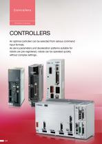
Product Lineup CONTROLLERS An optimal controller can be selected from various command input formats. As servo parameters and deceleration patterns suitable for robots are pre-registered, robots can be operated quickly without complex settings.
Open the catalog to page 1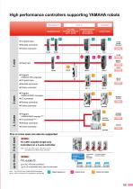
High performance controllers supporting YAMAHA robots TRANSERVO Stepping motor • I/O point trace • Remote command • Online command [T4L/T5L] Small type servomotor (24 V • 30 W) Linear motor • Pulse train Program •(YAMAHA SRC language) • I/O point trace • Remote command • Online command Program •(YAMAHA BASIC language) • I/O command • Remote command • Online command Program •(YAMAHA BASIC language) • I/O command • Remote command • Online command Five or more axes can also be supported RCX240 YC-LINK couples single-axis controllers to a 4-axis controller Note : Up to four SR1 series controllers...
Open the catalog to page 2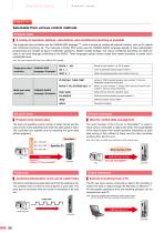
Product Lineup Program input | A variety of operation settings, calculations, and conditional branching is possible The single-axis robot controllers use the YAMAHA SRC language Note which is simple yet contains all required functions, such as I/O outputs and conditional branching, etc. The multi-axis controller RCX series uses the YAMAHA BASIC language capable of more sophisticated programming and includes all types of arithmetic operations, flexible variable settings, and various conditional branching, etc. Both are easy to use robot language conforming to the BASIC. These languages support...
Open the catalog to page 3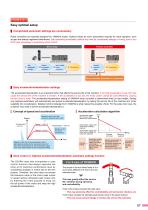
Easy optimal setup Complicated parameter settings are unnecessary Robot controllers are specially designed for YAMAHA robots. Optimal values for servo parameters required for robot operation, such as gain are already registered beforehand. Start operating immediately without any need for complicated settings or tuning, even if you don't have knowledge or experience about control. Servo amp Yamaha controller Control device and motion unit Gain adjustment (tuning) Motion 2. parameter settings Return-to-origin 3. System construction Control device Specify payload mass Servo parameter adjustment...
Open the catalog to page 4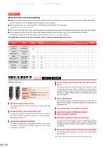
Product Lineup ControllersPOINT 3 Multi-function and expandability ■ Multi-axis controllers support up to 30,000 points (10,000 points for the RCX2 series, 1,000 points for the single-axis controller (255 points for the TS series)). Up to 100 programs can be created on each controller. ■ Various field networks, CC-Link, DeviceNet™, PROFIBUS, and EtherNet/IP™ are supported. Note. Some models do not support all networks. ■ The TS series, RD series, SR1 series, and RCX series use a dual-power supply system with separate control power supply and power supply. ■ As the controllers conform to the CE...
Open the catalog to page 5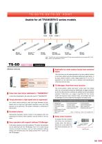
Note 1. The STH type vertical specifications and RF type sensor specifications do not support the TS-SD. Note 2. SG07 is only applicable to TS-SH. [Robot driver] Operation method | Pulse train input driver dedicated to "TRANSERVO" A robot driver dedicated to the pulse train input for "TRANSERVO". | Torque decrease in high-speed area is suppressed As a vector control method is used, the torque decrease in highspeed area is small and high-speed operation even with high payload can be performed. This greatly contributes to shortening of the tact time. | Excellent silence High-pitched operation sounds...
Open the catalog to page 6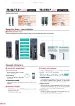
Product Lineup P.492 TRANSERVO TS-X/TS-P P.492 FLIP-X PHASER [Robot positioner] Operation method Operation method Design that allows a clean installation | Unified installation sizes Height and installation pitch are unified throughout the series. Units can be installed neatly within the control board. Absolute battery is neatly accommodated The absolute battery is stored inside the unit. Replacement can be performed easily from the front side. (TS-X and TS-SH supported) TS-X DIN rail installation On-board installation is made easy by the DIN rail installation mechanism that is standard on the...
Open the catalog to page 7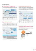
| "Positioner function" for easy positioning | Consecutive operation, linked operation You can easily perform positioning operations by specifying the number of a point that is registered in the data, and entering a start command. By specifying a branch destination, it is possible to execute positioning operations consecutively. Additionally, by specifying linked operation, operation with the branch destination can be executed while changing the speed without positioning stops; this allows control programming to be simplified and takt to be shortened. If jog input is within a specific time, inching...
Open the catalog to page 8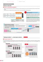
Product Lineup Remote commands are functions by which the control device can directly handle data such as points and parameters using the word area of the field network. Numerical data can be operated directly by using the word area. This promotes unification of data management. O: Parallel processing possible y Parallel processing is possible/ Big "Gateway function" — a new way to connect | Decrease network cost One controller equipped with a field network board can provide unified management of up to four I/O interfaces via a daisy-chain connection. This allows network cost to be decreased...
Open the catalog to page 9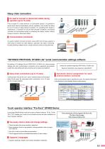
Daisy chain connection No need to connect or disconnect cables during operation (up to 16 units) From a single PC, handy terminal, or touch-panel display, it is possible to specify point data and parameters, perform operations, and monitor the status for up to 16 axes on daisy-chained controllers. For everything from design to maintenance, a connection to only the first controller is sufficient; any desired controller can be accessed simply by switching the station number, without having to connect or disconnect cables. Pro-face touch-panel Communication commands An easily handled command protocol...
Open the catalog to page 10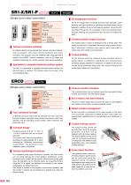
Product Lineup [Single-axis robot controller] Operation method | Various command methods An optimal method can be selected from various command methods, such as program, point trace, remote command, and online command. The program uses the YAMAHA SRC language that is similar to the BASIC. Various operations, such as I/O output and conditional branching, etc. can be executed using simple operations. | Applicable to complete absolute position system The SR1-X is applicable to complete absolute position system. No return-to-origin is needed. (The backup period is one year in the non-energizing state.)...
Open the catalog to page 11All Yamaha Motor Co.,Ltd. catalogs and technical brochures
 ROBOT CATLOG 2021-2022
771 Pages
 GF series
2 Pages
 R series
3 Pages
 SS series
6 Pages
 LCMR200
27 Pages
 YRG-2005SS
2 Pages
 YAMAHA Vision System Ivy2
6 Pages
 NEW SCARA ROBOT : YK400XE
6 Pages
 YAMAHA SCARA LINEUP Catalogue
95 Pages
 YAMAHA SCARA No.1
2 Pages
 Lineup Catalog
14 Pages
 Infomation
32 Pages
 Electric grippers
14 Pages
 ROBOT VISION iVY2
13 Pages
 Clean robots
44 Pages
 Pick & place robots
10 Pages
 SCARA robots
67 Pages
 Cartesian robots
128 Pages
 Linear motor single axis robots
27 Pages
 Single axis robots
46 Pages
 Vertically articulated robots
14 Pages
 YAMAHA ROBOT Catalog 2018
627 Pages


Archived catalogs
 YAMAHA ROBOT CATALOG 2020/2021
673 Pages
- Cylinder
- Actuator
- Industrial robot
- Transport rail conveyor
- Belt conveyor
- Linear actuator
- Electric actuator
- Positioning table
- Horizontal conveyor
- 6-axis robot
- Conveyor for the food industry
- Handling robot
- Floor-mounted robot
- Motorized positioning table
- Compact actuator
- Precision positioning table
- Electric drive conveyor
- Compact robot
- High-speed robot