Mti-600 Hardware Integration Manual
1 /17Pages

Mti-600 Hardware Integration Manual
1 /17Pages
Catalog excerpts

Hardware Integration Manual 1
Open the catalog to page 1
© 2005-2020, Xsens Technologies B.V. All rights reserved. Information in this document is subject to change without notice. Xsens, Xsens DOT, MVN, MotionGrid, MTi, MTi-G, MTx, MTw, Awinda and KiC are registered trademarks or trademarks of Xsens Technologies B.V. and/or its parent, subsidiaries and/or affiliates in The Netherlands, the USA and/or other countries. All other trademarks are the property of their respective owners.
Open the catalog to page 2
List of Tables Table Table Table Table
Open the catalog to page 3
Table Table Table Table Table List of Figures Figure Figure Figure Figure Figure Figure Figure Figure Figure
Open the catalog to page 4
This document provides hardware design instructions for the MTi 600-series module (MTi-600). The MTi-600 is a fully functional, self-contained module that is easy to design-in with limited external hardware components to be added. The MTi-600 can be embedded in an application by mounting it directly on a PCB or as a standalone module by connecting it via a flat-ribbon cable. The MTi-600 can be connected to a host through RS232, CAN or UART interfaces. The MTi 600-series Datasheet1 provides information on the usage and technical details of the MTi 600-series modules. The MTi 600-series module...
Open the catalog to page 5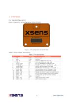
Figure 1 shows the pin configuration of the MTi-600.
Open the catalog to page 6
2.2 Communication to host The MTi-600 is designed to be used as a peripheral device in embedded systems or as a standalone unit. The MTi-600 supports Controller Area Network (CAN), RS232 and Universal Asynchronous Receiver/Transmitter (UART) protocols for the communication between the MTi-600 and a host. See Table 3 for interface specifications. For the physical connection recommendations, see section 4.3. Table 3: Host communication interfaces specifications A USB and RS422 interface is possible through a UART to USB/RS422 converter (see example in the MTi 600-series Development Kit). At its...
Open the catalog to page 7
Otherwise, it postpones transmission until CTS is raised. When during the transmission of a byte the user lowers the CTS signal, then the module completes transmission of that byte before postponing further output. The module will not retransmit this byte. Figure 2 shows the behaviour of the TX and CTS lines. Figure 3: RTS behaviour during data reception The user can use this communication mode without hardware flow control. In this case, the user must tie the CTS line high (e.g. VIN) to make the module transmit. 2.2.3 UART The UART interface can be used to directly connect to an MCU with 3.3...
Open the catalog to page 8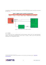
accordingly. Under default configurations, the PPS/TIMEPULSE output should be connected to SYNC_IN1 Table 4: GNSS receiver interface specifications Figure 4: Connections for the GNSS interface 2.4 SYNC The MTi-600 has two multifunctional synchronization inputs and one synchronization output. The electrical specifications can be seen in Table 7. Refer to the MTi 600-series Datasheet2 for configuration details. 2 Links to the latest available documentation can be found via the following link: Xsens MTi Documentation
Open the catalog to page 9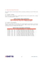
This section lists the recommended electrical operating conditions for the MTi-600 series module. 3.1 Supply voltage The MTi-600 series module has a single supply pin that can be supplied with a voltage within the range specified in Table 5. Table 5: Supply voltage specifications
Open the catalog to page 10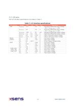
Table 7: I/O interface specifications
Open the catalog to page 11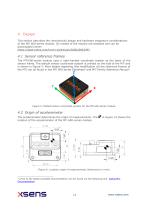
4 Design This section describes the (mechanical) design and hardware integration considerations of the MTi 600-series module. 3D models of the module are available and can be downloaded online: https://base.xsens.com/hc/en-us/articles/360023863393 4.1 Sensor reference frames The MTi 600-series module uses a right-handed coordinate system as the basis of the sensor frame. The default sensor coordinate system is printed on the side of the MTi and is shown in Figure 5. More details regarding (the modification of) the reference frames of the MTi can be found in the MTi 600-series Datasheet3 and MTi...
Open the catalog to page 12
4.3 Physical connections The connector on the MTi-600 series module is a 16 pins, 1.27 mm pitch male connector of Phoenix Contact (FP 1,27/ 16-MV 1,75 – 1714936). This connector supports an SMD counterpart that can be soldered onto a PCB as well as a ribbon cable (IDC) counterpart. In order to mount the MTi-600 onto a PCB, the connector should be facing down and the MTi-600 housing should be supported with M2 spacers that can be soldered onto the PCB. When using a ribbon cable the MTi-600 can be mounted upside-down to create easy access to the connector. Figure 7 shows both mounting options....
Open the catalog to page 13
Table 8: Recommended mating/mounting parts
Open the catalog to page 14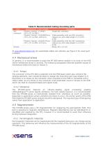
Table 9: Recommended mating/mounting parts Part Manufacturer + part number Description At www.phoenixcontact.com pre-assembled cables can ordered, see Figure 9 for exact part numbers. 4.4 Mechanical stress In general, it is recommended to place the MTi 600-series module in an area on the PCB where mechanical stress is minimal. The following paragraphs describe possible causes of mechanical stress and ways to reduce it. 4.4.1 Torque The connector of the MTi-600 is soldered onto the PCB board which also contains the sensing elements. Care should be taken to design the mounting such (see chapter...
Open the catalog to page 15
Therefore, it is recommended to keep these ferromagnetic materials away from the MTi 600-series. 4.5.2 High currents High current power lines on the PCB will introduce magnetic fields that may influence the measurements of the 3D magnetometer of the MTi 600-series. Place high current power lines away from the MTi 600-series. Example: a power line with a current of 100 mA at a distance of 10 mm from the magnetometer, will introduce an error of 2 µT. More information on magnetic interference can be found in the MTi Family Reference Manual4. Static magnetic disturbances can be calibrated for, see...
Open the catalog to page 16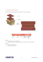
The MTi 600-series packaging boxes contain from 5 up to 20 modules. NOTES: • All dimensions are in millimeters. • Pictured tray and box representative only, actual tray may look different. CONTENT: • 5 to 20 modules per box. • Calibration certificate.
Open the catalog to page 17All Xsens catalogs and technical brochures
 Mti-600 Leaflet
2 Pages
 Mti-600 DK Manual
22 Pages
 MTi-600 Datasheet
33 Pages
 MTw Awinda
2 Pages
 MTi-G-710 Leaflet
2 Pages
 MTi 100-series Leaflet
2 Pages
 MTi 10-series Leaflet
2 Pages
 MTi-7 Leaflet
2 Pages
 MTi 1-series Data Sheet
35 Pages


- Automation software solution
- Analysis software solution
- Sanxing Electric real-time software
- Control software
- 3D software solution
- Measurement software
- Quality software
- Visualization software solution
- Calibration software
- Standby tracker
- INS
- Office software
- GNSS inertial navigation system
- Inertial measurement unit
- High-accuracy inertial navigation system
- Lightweight inertial navigation system
- Motion sensor
- Miniature inertial navigation system
- Attitude and heading reference system
- Animation software