MTi 1-series Data Sheet
1 /35Pages

MTi 1-series Data Sheet
1 /35Pages
Catalog excerpts

MTi 1-series Data SheetIMU, VRU, AHRS and GNSS/INS moduleDocument MT0512P, Revision G, 11 Jan 2019 Xsens Technologies B.V. Xsens North America, Inc. 10557 Jefferson Blvd, Suite C CA-90232 Culver City USA phone 310-481-1800 fax 310-416-9044 e-mail [email protected] internet www.xsens.com
Open the catalog to page 1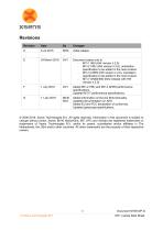
© 2005-2019, Xsens Technologies B.V. All rights reserved. Information in this document is subject to change without notice. Xsens, MVN, MotionGrid, MTi, MTx and Awinda are registered trademarks or trademarks of Xsens Technologies B.V. and/or its parent, subsidiaries and/or affiliates in The Netherlands, the USA and/or other countries. All other trademarks are the property of their respective owners. © Xsens Technologies B.V. MTi 1-series Data Sheet
Open the catalog to page 2
© Xsens Technologies B.V. MTi 1-series Data Sheet
Open the catalog to page 3
1. General information This document provides information on the contents and usage of the MTi 1-series modules. The MTi 1-series module (MTi 1-s) is a fully functional, self-contained module that is easy to design-in. The MTi 1-s can be connected to a host through I2C, SPI or UART interfaces. The Hardware Integration Manual: MTi 1-series (MT1503) supplements this document. Notes on typical application scenarios, recommended external components, printed circuit board (PCB) layout, origin of measurements, stress related considerations, reference designs and handling information could be found...
Open the catalog to page 5
1.2 Identifying device functionality using the unique Device Identifier Each Xsens product is marked with a unique serial device identifier referred to as the Device ID. The Device ID is categorized per MTi product configuration in order to make it possible to recognize the MTi by reviewing the Device ID. The second digit of the Device ID denotes the functionality (e.g. ‘1’ for all IMU products, such as MTi-1, MTi-10 and MTi-100), the third digit denotes the product series (6 for MTi 10-series, 7 for MTi 100-series, 8 for MTi 1-series) and the fourth digit denotes the interface (always 8 for...
Open the catalog to page 6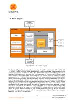
Block diagram Figure 1: MTi 1-series module diagram The diagram in Figure 1 shows a simplified organization of the MTi 1-series module (MTi 1-s). The MTi 1-s contains a 3-axis gyroscope, 3-axis accelerometer, 3-axis magnetometer, a high-accuracy crystal and a low-power micro controller unit (MCU). The MTi-7 module can also accept the signals from an external GNSS receiver and/or barometer. The MCU coordinates the timing and synchronization of the various sensors. The module offers the possibility to use external signals in order to accurately synchronize the Mti 1-s with any user application....
Open the catalog to page 7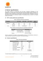
2. Sensor specifications This section presents the performance and the sensor component specifications for the calibrated MTi 1-s module. Each module goes through the Xsens calibration process individually. The calibration procedure calibrates for many parameters, including bias (offset), alignment of the sensors with respect to the module PCB and each other and gain (scale factor). All calibration values are temperature dependent and temperature calibrated. The calibration values are stored in non-volatile memory of the module. 2.1 MTi 1-series performance specifications Table 3: Orientation...
Open the catalog to page 8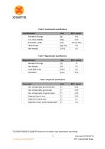
Table 6: Accelerometer specifications 2 As Xsens continues to update the sensors on the module, these specifications may change 5 Document MT0512P.G © Xsens Technologies B.V. MTi 1-series Data Sheet
Open the catalog to page 9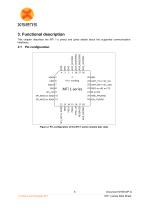
3. Functional description This chapter describes the MTi 1-s pinout and gives details about the supported communication interfaces. Figure 2: Pin configuration of the MTi 1-series module (top view) Document MT0512P.G MTi 1-series Data Sheet
Open the catalog to page 10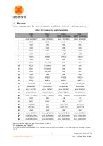
Table 9: Pin mapping for peripheral selection 3 AUX and SYNC_PPS pins are only available on MTi-7 4 I2C addresses, see Table 13. 5 CTS cannot be left unconnected if the interface is set to UART full duplex. If HW flow control is not used, connect o GND. © Xsens Technologies B.V. MTi 1-series Data Sheet
Open the catalog to page 11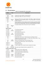
Table 10: Pin description MTi 1-series module © Xsens Technologies B.V. MTi 1-series Data Sheet
Open the catalog to page 12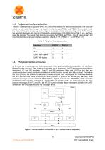
3.4 Peripheral interface selection The MTi 1-series module supports UART, I2C, and SPI interfaces for host communication. The host can select the active interface through the peripheral selection pins PSEL0 and PSEL1. The module reads the state of these pins at start-up, and configures its peripheral interface according Table 11. To change the selected interfaces, the host must first set the desired state of the PSEL0 and PSEL1 pins, and then reset the module. The module has internal pull-ups on the PSEL0 and PSEL1 pins. If these pins are left unconnected, the peripheral interface selection defaults...
Open the catalog to page 13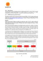
3.4.2 Xbus Protocol The Xbus protocol is Xsens’ proprietary protocol for interfacing with the MTi 1-series. The MT Low Level Communication Protocol Documentation is a complete reference for the protocol. For a better understanding of the MTSSP explanation, the advice is to read the protocol reference first. 3.4.3 MTSSP Synchronous Serial Protocol This Section specifies the MTi Synchronous Serial Protocol (MTSSP). The MTi 1-series module uses MTSSP as the communication protocol for both the I2C and SPI interfaces. The ARM® mbedTM example program (see https://developer.mbed.org/teams/Xsens), provides...
Open the catalog to page 14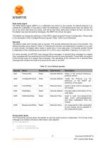
Data ready signal The Data Ready Signal (DRDY) is a notification line driven by the module. Its default behavior is to indicate the availability of new data in either the Notification- or the Measurement pipe. By default, the line is low when both pipes are empty, and will go high when either pipe contains an item. As soon as the Master has read all pending messages, the DRDY line will go low again. The Master can change the behaviour of the DRDY signal using the Procotol Configuration. Please refer to the description of the ConfigureProtocol opcode (Table 12)for more information. Opcodes The...
Open the catalog to page 15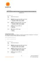
m drdyConfig: Bits Reserved for future use 7:4 Bit 3 MEVENT: Measurement pipe DRDY event enable 0 : Generation of DRDY event is disabled 1 : Generation of DRDY event is enabled Bit 2 NEVENT: Notification pipe DRDY event enable 0 : Generation of DRDY event is disabled 1 : Generation of DRDY event is enabled Bit 1 OTYPE: Output type of DRDY pin 0: Push/pull 1: Open drain Bit 0 POL: Polarity of DRDY signal 0: Idle low 1: Idle high ConfigureProtocol (0x02) The ProtocolInfo opcode allows the Master to change the active protocol configuration. The format of the message is as follows (All data is...
Open the catalog to page 16All Xsens catalogs and technical brochures
 Mti-600 Leaflet
2 Pages
 Mti-600 DK Manual
22 Pages
 MTi-600 Datasheet
33 Pages
 MTw Awinda
2 Pages
 MTi-G-710 Leaflet
2 Pages
 MTi 100-series Leaflet
2 Pages
 MTi 10-series Leaflet
2 Pages
 MTi-7 Leaflet
2 Pages


- Automation software solution
- Analysis software solution
- Sanxing Electric real-time software
- Control software
- 3D software solution
- Measurement software
- Quality software
- Visualization software solution
- Calibration software
- Standby tracker
- INS
- Office software
- GNSS inertial navigation system
- Inertial measurement unit
- High-accuracy inertial navigation system
- Lightweight inertial navigation system
- Motion sensor
- Miniature inertial navigation system
- Attitude and heading reference system
- Animation software