
- Catalogs
- Xiamen SET electronics Co.,Ltd
- XG Series Ir : 3 A


- Company
- Products
- Catalogs
- News & Trends
- Exhibitions
XG Series Ir : 3 A

XG Series Ir : 3 A
- Transparent plastic case
- Non-resettable
- High accuracy of functioning temperature
- RoHS & REACH compliant
- Different temperatures
- Lead wire length
- Taping packing
- Insulated lead wires
- Tinned copper or CP wires
The ATCO Thermal-Link is a non-resettable protective device used in electrical equipment. It consists of a fusible alloy, flux resin, case, sealant, and lead wires. It functions by melting the fusible alloy under abnormal temperature conditions, disconnecting the circuit.
- Lamps
- Switched-mode power supplies
- Home electrical appliances
- Batteries
The XG Series has a rated current of 3A and various models with different rated functioning temperatures (Tf) ranging from 76°C to 221°C. The devices are certified under multiple standards including UL, CAN-CSA, EN, and others.
- Ensure installation temperature does not exceed the maximum temperature limit (Tm).
- Avoid placing in areas with severe vibration.
- Ensure lead wires are not under stress or damaged.
- Riveting should use materials with low resistivity.
- Soldering should follow specified parameters to avoid premature functioning.
Available in bulk and taping options with specific dimensions and quantities.
The document outlines the specifications for hand-soldering and wave soldering of ATCO components. It includes detailed tables specifying the maximum allowable soldering time and temperature for different lead wire lengths. The hand-soldering time varies based on the rated functioning temperature (Tf) and lead wire length (Ls), with auxiliary heat sink fixtures required for certain conditions to prevent unexpected cutting off of ATCO.
For temperatures ranging from 76°C to 230°C, the maximum soldering time is specified for lead wire lengths of 10mm, 20mm, and 30mm, with corresponding times increasing with temperature.
When bending lead wires, maintain a specified distance between the body and bending point as per Table XG-3. Use appropriate tools to avoid damaging the product, and avoid tangential forces on the leads to prevent damage to the ATCO seal.
The document provides parameters for preheating, wave soldering, and cooling times. For temperatures between 131°C and 230°C, specific preheating and wave soldering temperatures are recommended, with maximum allowable times for each stage.
- Use auxiliary heat sink fixtures when necessary.
- Avoid cutting, nicking, or sharply bending lead wires.
- Ensure proper handling to prevent damage to the ATCO seal.
- Figure XG-1 and XG-2 illustrate the soldering and fixing positions, respectively.
- Tables XG-1, XG-2, and XG-3 provide detailed specifications for soldering times, temperatures, and lead wire forming distances.
Catalog excerpts

Description Alloy Thermal-Link / Alloy Thermal Cutoff (ATCO) is defined as a non-resettable protective device functioning one time only. It is widely used in electrical equipment. ATCO is mainly consist of fusible alloy, flux resin, case, sealant and lead wires. Normally, fusible alloy is jointed to the two lead temp. of ATCO, the fusible alloy melts and quickly retracts to the two lead wire ends with the aid of the flux resin and disconnects the circuit completely. Transparent Plastic Case Switched-Mode Power Supplies High Accuracy of Functioning Temp. Home Electrical Appliances Make a Mounting Hole RoHS & REACH Compliant Other Temp. The Length of Lead Wires Taping Packing Available Lead Wires can be Insulated Tinned Copper Wires or CP Wires +86 592-5715-838 www.SETsafe.com www.SETfuse.com E-mail : [email protected] All Rights Reserved by Xiamen SET Electronics Co., Ltd. 2021-2023 V2.0 wires. Under abnormal conditions, whe
Open the catalog to page 1
Agency Approvals File No. Structure Diagrams Fusible Alloy Flux Resin Case Sealant Lead Wire Before Functioning After Functioning Trademark Rated Functioning Temp. Model Agency Mark Date Code RoHS & REACH +86 592-5715-838 www.SETsafe.com www.SETfuse.com E-mail : [email protected] All Rights Reserved by Xiamen SET Electronics Co., Ltd. 2021-2023 V2.0
Open the catalog to page 2
Part Numbering System ATCO - XG 2 - A N N A B - 001 Packing B: Bulk T: Taping Leads Forming A: Straight Lead Color of Insulation Tube W: White Y: Yellow N: None Insulation Tube Material T: Teflon P: Polyester N: None Lead Wire Type A: Tinned Copper Wire B: Tinned Copper Plated Wire Rated Functioning Temp. 2: 115 °C, See Specifications Series XG Product Category ATCO +86 592-5715-838 www.SETsafe.com www.SETfuse.com E-mail : [email protected] All Rights Reserved by Xiamen SET Electronics Co., Ltd. 2021-2023 V2.0 Other Options
Open the catalog to page 3
Glossary Item Description Thermal-Link A non-resettable device incorporating a THERMAL ELEMENT which will open a circuit once only when exposed for a sufficient length of time to a temperature in excess of that for which it has been designed. Alloy Thermal-Link Alloy Type Thermal-Link, Alloy is the thermal element. Rated Functioning Temp. The temperature of the Alloy Thermal-Link which causes it to change the state of conductivity with a detection current up to 10 mA as the only load. Tolerance: Tf Tolerance: Tf ± 7 °C (J60691). Fusing Temp. Fusing Temp. The temperature of the Alloy Thermal-Link...
Open the catalog to page 4
Fusing Temp. RoHS、 REACH
Open the catalog to page 5
Product Temp.-Time Curve (Reference) The Temp.-Time Curve of Thermal-Link in different temp. oil bath. +86 592-5715-838 www.SETsafe.com www.SETfuse.com E-mail : [email protected]
Open the catalog to page 6
Product Current-Time Curve (Reference) The Current-Time Curve shows functioning time at multi-times rated current at room temperature 25 ± 2 °C. +86 592-5715-838 www.SETsafe.com www.SETfuse.com E-mail : [email protected] All Rights Reserved by Xiamen SET Electronics Co., Ltd. 2021-2023 V2.0
Open the catalog to page 7
Packaging Information Bulk PE Bag +86 592-5715-838 www.SETsafe.com www.SETfuse.com E-mail : [email protected] All Rights Reserved by Xiamen SET Electronics Co., Ltd. 2021-2023 V2
Open the catalog to page 8
+86 592-5715-838 www.SETsafe.com www.SETfuse.com E-mail : [email protected] All Rights Reserved by Xiamen SET Electronics Co., Ltd. 2021-2023
Open the catalog to page 9
Attention Usage Mechanical Connection 1. When atmosphere pressure is from 80 kPa to 106 kPa, the operating current less than rated current of ATCO. 3. Do not touch the ATCO body or lead wires directly when power is on, to avoid burn or electric shock. 1. Choose small resistivity riveting material and be riveted. 2. A flexible lead or lead with low resistance should be used to rivet the ATCO. 3. Contact resistance should be minimal, Large contact resistance will lead to higher temp., ATCO Functioning in advance. Replace ATCO is a non-repairable product. For safety sake, it shall be replaced by...
Open the catalog to page 10
Thermal-Link TABLE XG-1 Hand-Soldering Time Max. Allowable Soldering Time for Different Lead Wire Length (Fig.XG-1) Ls Length Tinned Copper Wire Tinned Copper Wire Time Tinned Copper Wire Note: a: Auxiliary Heat Sink Fixture is Required to Avoid ATCO Cutting off Unexpectedly. TABLE XG-2 Wave Soldering Parameters Setting Rated Functioning Temp. (Tf) Max. Allowable Preheating Temp. When the Length of Lead Wire is Different (Fig.KG-1) Ls Preheating Ls Preheating Length Temp. Length Temp. (mm) Preheating Max. Dwelling Time Wave Time (t1) Soldering (t2) Temp. Recommend Hand-Soldering Max. Wave Soldering...
Open the catalog to page 11
Lead Wire Forming 1. If lead wire has to be bent, please pay attention to the distance between body and bending point. Refer to Table XG-3. fix the product as shown in Fig.XG-2, to avoid damaging the 2. When bending leads, please use pincher or similar tools to product. 3. During forming and mounting, lead wire should not be cut, nicked, bent sharply, to avoid breaking the product. 4. Tangential forces on the leads must be avoided (i.e. pushing or pulling on the leads at angle to ATCO body) as such forces may damage the seal of ATCO. TABLE XG-3 Distance between Body and Bending Point d +86 592-5715-838...
Open the catalog to page 12
ATTENTION Usage 1. When atmosphere pressure is from 80 kPa to 106 kPa, the related altitude shall be from 2000 meter to - 500 meter. 2. Operating voltage less than rated voltage of ATCO, operating current less than rated current of ATCO. 3. Do not touch the ATCO body or lead wires directly when power is on, to avoid burn or electric shock. Replace ATCO is a non-repairable product. For safety sake, it shall be replaced by an equivalent ATCO from the same manufacturer, and mounted in the same way. Storage Do not store the ATCO at the high temp., high humidity or corrosive gas environment, avoid...
Open the catalog to page 13
Mechanical Connection Riveting 1. Choose small resistivity riveting material and be riveted. 2. A flexible lead or lead with low resistance should be used to rivet the ATCO. Soldering Hand-Soldering 1. Soldering should be carried out according to Table XG-1. 2. The thermal element of ATCO is fusible alloy with low melting point, which is jointed with ATCO lead wires. Improper soldering operation (too high soldering temp. , too long soldering time, too short lead wire etc.) may transfer more heat to the thermal element and ATCO may open in advance. 3. When soldering conditions are more severe...
Open the catalog to page 14All Xiamen SET electronics Co.,Ltd catalogs and technical brochures
 SKL Series Ir : 10 A
14 Pages
 SK Series Ir : 10 A
15 Pages
 SY Series Ir : 10 A
14 Pages
 Q Series Ir : 25 A
15 Pages
 TM Series Ir : 15 / 16 A
15 Pages
 SMF Series
14 Pages
 YM Series Ir : 5 A
15 Pages
 K Series Ir : 2 A
16 Pages
 TPH×××-R Series
10 Pages
 Y Series Ir : 5 A
16 Pages
 SC625 series
11 Pages
 F Series
15 Pages
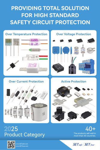 E-All Products Catalog(2024-2026)
148 Pages
 HS Series Ir : 5 A
10 Pages
 SD Series Ir : 10 A
11 Pages
 XM Series Ir : 3 A
11 Pages
 T Series Ir : 15 / 16 A
11 Pages
 P Series Ir : 20 A
10 Pages
 TK Series Ir : 15 / 16 A
11 Pages
 S Series Ir : 10 A
11 Pages
 KM Series Ir : 2 A
11 Pages
 SM Series Ir : 10 A
11 Pages
 KG Series Ir : 2 A
12 Pages
Archived catalogs
 X Series Ir : 3 A
12 Pages
- Surge protector
- DIN rail lightning arrester
- Power supply lightning arrester
- Low-voltage lightning arrester
- Class II surge arrester
- AC surge arrester
- Diode
- Remote signaling surge arrester
- Varistor surge arrester
- Wire-wound resistor
- Photovoltaïc installation surge arrester
- Surge arrester for telecom applications
- Voltage diode
- Power resistor
- Fast-acting fuse
- High-voltage diode
- Cylindrical fuse
- MOV surge arrester
- Class I surge arrester
- Avalanche diode