- Catalogs
- Xiamen SET electronics Co.,Ltd
- SMF Series
SMF Series
1 /14Pages

SMF Series
1 /14Pages
Catalog excerpts

Transient Voltage Suppression Diodes SMF Series Description The SMF series is designed specifically to protect sensitive electronic equipment from voltage transients induced by lightning and other transient voltage events. SMF package is 50% smaller in footprint when compare to SMA package and delivering one of the low height profiles (1.2mm) in the industry. • Communication Equipment • Security & Protection • Industrial Control Equipment • Power Supply • Automotive Electronics • Lightning Protection • 200 W peak pulse capability at 10/1000 ps waveform, repetition rate (duty cycles):0.01% • Compatible with industrial standard package SOD-123FL • Low profile: maximum height of 1.2 mm • Low inductance, excellent clamping capability • For surface mounted applications to optimize board space • High temperature to reflow soldering guaranteed: 260 °C / 40 sec • Typical failure mode is short from over-specified voltage or current • Whisker test is conducted based on JEDEC JESD201A per its table 4a and 4c • ESD protection of data lines in accordance with IEC 61000-4-2 • EFT protection of data lines in accordance with IEC 61000-4-4 • Fast response time: typically less than 1.0 ns from 0 Volts to Vbr min • Built-in strain relief • Plastic package is flammability rated V-0 per UL 94 • Matte tin lead-free plated • Halogen-free and RoHS compliant • Pb-free E3 means 2nd level interconnect is Pb-free and the terminal finish material is tin(Sn) (IPC/ JEDEC J-STD-609A.01) All Rights Reserved by Xiamen SET Electronics Co., Ltd. 2024-2026 V1.4 +86 592-571-5838 www.SETsafe.comwww.SETfuse.com E-mail : [email protected]
Open the catalog to page 1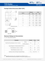
Transient Voltage Suppression Diodes SMF Series Package Outline Dimensions (SOD-123FL) Mounting Pad Layout (Ta = 25 °C unless otherwise specified.) 1. Non-repetitive current pulse, per Fig. 4 and derated above T (initial)=25 °C per Fig. 2. SMF90A~SMF100A Peak Pulse Power Dissipation is 170 W min, 200 W typical @ 10/1000 us. All Rights Reserved by Xiamen SET Electronics Co., Ltd. 2024-2026 V1.4 +86 592-571-5838 www.SETsafe.comwww.SETfuse.com E-mail : [email protected]
Open the catalog to page 2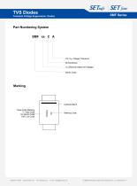
Transient Voltage Suppression Diodes Part Numbering System SMF xx C A 5% VBR Voltage Tolerance Bi-directional VR (Reverse Stand-off Voltage) Series Code Cathode Band Trace Code Marking Y: Year Code M: Month Code XXX: Lot Code Marking Code E-mail : [email protected] All Rights Reserved by Xiamen SET Electronics Co., Ltd. 2024-2026 V1.4 3
Open the catalog to page 3
Transient Voltage Suppression Diodes SMF Series Electrical Characteristics (Ta=25 °C unless otherwise noted ) +86 592-571-5838 www.SETsafe.comwww.SETfuse.com E-mail : [email protected] All Rights Reserved by Xiamen SET Electronics Co., Ltd. 2024-2026 V1.4
Open the catalog to page 4
Transient Voltage Suppression Diodes SMF Series Part Number 1. VBR measured after IT applied for 300 |js, IT = square wave pulse or equivalent. 2. Surge current waveform per 10/1000 js exponential wave and derated per Fig.2. 3. All terms and symbols are consistent with ANSI/IEEE C62.35. 4. For bidirectional type having VR of 10 volts and less, the IR should be doubled. +86 592-571-5838 www.SETsafe.comwww.SETfuse.com E-mail : [email protected] All Rights Reserved by Xiamen SET Electronics Co., Ltd. 2024-2026 V1.4
Open the catalog to page 5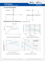
Transient Voltage Suppression Diodes Performance Curve for Reference(TA=25 °C unless otherwise noted) 10 PPPM - Peak Pulse Power (KW) Voltage Transient FIGURE 2 Peak Pulse Power Rating Curve FIGURE 1 TVS Transients Clamping Waveform 150 IPPM - Peak Pulse Current, % IRSM Peak Pulse Power (PPP) or Current (IPPM) Derating in Percentage, % FIGURE 3 Peak Pulse Power Derating Curve 100 Half Value IPPM/2 10/1000 μs Waveform as defined by R.E.A. TJ –Initial Junction Temperature (°C ) Peak Value IPPM TJ = 25 °C Pulse Width (td) is defined as the Point where the Peak Current decays to 50 % of IPPM FIGURE...
Open the catalog to page 6
Transient Voltage Suppression Diodes FIGURE 8 Maximum Non-Repetitive Forward Surge Current Uni-Directional only Physical Specifications Environmental Specifications High Temp. Storage All Rights Reserved by Xiamen SET Electronics Co., Ltd. 2024-2026 V1.4 +86 592-571-5838 www.SETsafe.comwww.SETfuse.com E-mail : [email protected]
Open the catalog to page 7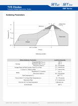
Transient Voltage Suppression Diodes Soldering Parameters TS (max) Ramp-down TS (min) tS Preheat 25 °C t 25 °C to Peak Time (t) Reflowing Condition Reflow Soldering Parameters Temperature Min (TS (min)) Temperature Max (TS (max)) Time (min to max) (tS) Average Ramp Up Rate (Liquidus Temp (TL) to Peak Lead-Free Assembly Time of within 5 °C of Actual Peak Temperature (tP) Ramp-down Rate Time from 25 °C to Peak Temperature E-mail : [email protected] All Rights Reserved by Xiamen SET Electronics Co., Ltd. 2024-20
Open the catalog to page 8
Transient Voltage Suppression Diodes SMF Series Packaging Information Part Number +86 592-571-5838 www.SETsafe.comwww.SETfuse.com E-mail : [email protected] All Rights Reserved by Xiamen SET Electronics Co., Ltd. 2024-2026 V1.4
Open the catalog to page 9
Transient Voltage Suppression Diodes SMF Series Glossary Item +86 592-571-5838 www.SETsafe.comwww.SETfuse.com E-mail : [email protected] All Rights Reserved by Xiamen SET Electronics Co., Ltd. 2024-2026 V1.4
Open the catalog to page 10
Transient Voltage Suppression Diodes ATTENTION Usage 1. TVS must be operated in the specified ambient temp. 2. Do not clean the TVS with strong polar solvent such as ketone, esters, benzene and halogenated hydrocarbon, to avoid damaging the encapsulating layer. 3. Please do not apply severe vibration, shock or pressure to TVS, to avoid element cracking. 1. If TVS is visually damaged, please replace it. 2. TVS is a non-repairable product. For safety sake, please use equivalent TVS for replacement. 1. Storage Temp. Range: (-55 to 150) °C. 2. Do not store the TVS at the high temp., high humidity...
Open the catalog to page 11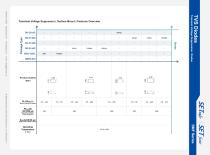
E-mail : [email protected] Transient Voltage Suppression Diodes All Rights Reserved by Xiamen SET Electronics Co., Ltd. 2024-2026 V1.4
Open the catalog to page 12All Xiamen SET electronics Co.,Ltd catalogs and technical brochures
 SKL Series Ir : 10 A
14 Pages
 SK Series Ir : 10 A
15 Pages
 SY Series Ir : 10 A
14 Pages
 Q Series Ir : 25 A
15 Pages
 TM Series Ir : 15 / 16 A
15 Pages
 YM Series Ir : 5 A
15 Pages
 K Series Ir : 2 A
16 Pages
 TPH×××-R Series
10 Pages
 Y Series Ir : 5 A
16 Pages
 SC625 series
11 Pages
 F Series
15 Pages
 E-All Products Catalog(2024-2026)
148 Pages
 HS Series Ir : 5 A
10 Pages
 SD Series Ir : 10 A
11 Pages
 XM Series Ir : 3 A
11 Pages
 T Series Ir : 15 / 16 A
11 Pages
 P Series Ir : 20 A
10 Pages
 TK Series Ir : 15 / 16 A
11 Pages
 XG Series Ir : 3 A
15 Pages
 S Series Ir : 10 A
11 Pages
 KM Series Ir : 2 A
11 Pages
 SM Series Ir : 10 A
11 Pages
 KG Series Ir : 2 A
12 Pages
Archived catalogs
 X Series Ir : 3 A
12 Pages
- Surge protector
- DIN rail lightning arrester
- Power supply lightning arrester
- Low-voltage lightning arrester
- Class II surge arrester
- AC surge arrester
- Remote signaling surge arrester
- Varistor surge arrester
- Wire-wound resistor
- Photovoltaïc installation surge arrester
- Surge arrester for telecom applications
- Voltage diode
- Power resistor
- Fast-acting fuse
- High-voltage diode
- MOV surge arrester
- Class I surge arrester
- Cylindrical fuse
- Avalanche diode