

- Products
- Catalogs
- News & Trends
- Exhibitions
KS33-F
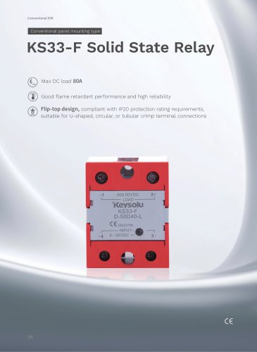
KS33-F
Overview
The KS33-F series is a conventional panel-mount type Solid State Relay (SSR) designed for DC output applications. It features MOSFET output technology, photoelectric isolation, and a flip-top design compliant with IP20 protection. The SSR supports a wide range of input and output voltages and currents, making it suitable for various industrial and medical applications.
Key Features
- MOSFET output for efficient switching
- Photoelectric isolation between input and output with 2500V dielectric strength
- Low on-state resistance for reduced power loss
- Panel mount design with flip-top cover
- Input control voltage range: 4 to 32 VDC
- Output voltage options: 50V, 100V, 400V DC
- Output current ratings from 10A to 80A
- Good flame retardant performance and high reliability
- Suitable for U-shaped, circular, or tubular crimp terminal connections
Applications
Primarily used in lithium battery systems, testing and inspection equipment, and medical devices.
Model Selection Guide
The KS33-F series includes various models differentiated by load voltage and current ratings, for example:
- KS33-F/D-50D40-L: 50V load voltage, 40A current
- KS33-F/D-50D80-L: 50V load voltage, 80A current
- KS33-F/D-100D40-L: 100V load voltage, 40A current
- KS33-F/D-100D80-L: 100V load voltage, 80A current
- KS33-F/D-400D10-L: 400V load voltage, 10A current
General Specifications (at 25°C)
- Input control voltage: 4 to 32 VDC
- Must turn-on voltage: 4 VDC
- Must turn-off voltage: 1 VDC
- Max input current: 28 mA at 32 VDC
- Max reverse protection voltage: -32 VDC
- Insulation resistance: 1000 MΩ (at 500 VDC)
- Dielectric strength: 2500 VAC (input/output/base) for 1 minute
- Vibration resistance: 10-55 Hz, 1.5 mm amplitude
- Shock resistance: 980 m/s²
- Operating temperature range: -30°C to 80°C
- Storage temperature range: -30°C to 100°C
- Weight: Approximately 100 g
Output Specifications (at 25°C)
- Load voltage ranges: 3-50 VDC, 3-100 VDC, 3-400 VDC depending on model
- Load current ranges: 10A, 40A, 80A options
- Max off-state leakage current: 0.1 mA
- Max on-state voltage drop: varies by model (e.g., 0.64 V for 40A)
- Max on-state resistance: ranges from 8 mΩ to 37.5 mΩ
- Max turn-on and turn-off times: 2 ms each
- Max surge current (10 ms): varies by model, e.g., 100 A peak for some
Mechanical and Wiring Details
The SSR features panel mounting holes and a wiring diagram suitable for control signal and load connections. The design supports various terminal types for secure connections.
Characteristic Curves and Thermal Performance
Graphs illustrate the relationship between ambient temperature and maximum load current for different models, both with and without heat sinks. Heat sinks such as HF92B-80, HF92B-150A, and HF92B-120 improve current handling capacity. Fan cooling with specified airflow (≥5 CFM or ≥20 CFM) further enhances performance.
Additional curves show the maximum permissible non-repetitive peak surge current versus energizing continuance time, providing guidance on transient current handling.
Critical Parameters and Recommendations
- Ensure control voltage remains within 4-32 VDC for reliable operation.
- Observe maximum load current limits relative to ambient temperature and cooling conditions.
- Use appropriate heat sinks and cooling fans to maintain SSR within safe operating temperatures under high load.
- Follow wiring diagrams carefully to ensure correct control and load connections.
- Note dielectric strength and isolation ratings to maintain safety and prevent damage.
Summary
The KS33-F series SSRs provide versatile, reliable DC switching solutions with multiple voltage and current options. Their robust design, including photoelectric isolation and MOSFET output, ensures high performance in demanding applications such as battery management, medical devices, and testing equipment. Proper thermal management and adherence to electrical specifications are essential for optimal operation.
Catalog excerpts
Conventional panel mounting type KS33-F Solid State Relay Max DC load ��A Good flame retardant performance and high reliability Flip-top design, compliant with IP20 protection rating requirements, suitable for U-shaped, circular, or tubular crimp terminal connections
Open the catalog to page 1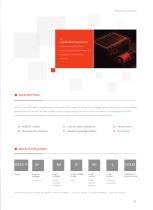
Panel Mount ‒ DC Output Application Scenarios: Primarily used in lithium batteries, testing and inspection equipment, and medical devices. KS33-F is an SPST-NO DC output panel mount type SSR. It offers 4~32VDC input voltage option and seven DC output voltage options from 50V to 400V as well as eight output current ratings from 10A to 80A for selection. The SSR adopts MOSFET output and provides photoelectric isolation between input and output with dielectric strength 2500V. MOSFET output Panel mount Photoelectric isolation Control voltage Load voltage Load voltage mode Load current Load current...
Open the catalog to page 2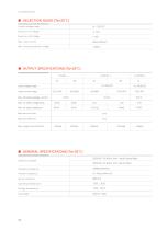
Must turn-on voltage Must turn-off voltage Max. reverse protection voltage Control voltage range Max. off-state leakage current Max. on-state voltage drop Load voltage range Load current range Insulation resistance Vibration resistance Shock resistance Operating temperature Storage temperature Unit weight Dielectric strength
Open the catalog to page 3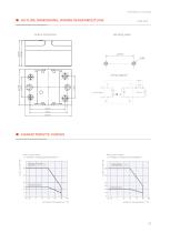
Panel Mount ‒ DC Output ■ OUTLINE DIMENSIONS, WIRING DIAGRAMOUTLINE Mounting Holes Outline Dimensions Wiring Diagram Control signal Max. Load Current vs. Ambient Temperature (D-50D80-L) Load Current (A) Max. Load Current vs. Ambient Temperature(D-50D40-L) WWith a HF92B-80 heat sink With a HF92B150A heat sink Without heat sink Without heat sink Ambient Temperature
Open the catalog to page 4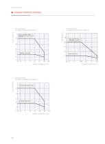
Without heat sink With a HF92B-150C heat sink Without heat sink With a HF92B-120 heat sink Without heat sink Peak Surge Current (A) Max. Load Current vs. Ambient Temperature (D-400D10-L) Peak Surge Current (A) Peak Surge Current (A) With a HF92B-150A heat sink Fan air volume ≥20CFM Max. Load Current vs. Ambient Temperature (D-100D80-L) Load Current (A) Max. Load Curren vs. AmbientTemperatur
Open the catalog to page 5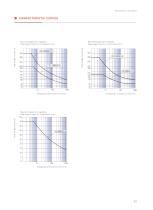
Panel Mount ‒ DC Output Max. Permissible Non-repetitive Peak Surge Current vs. Continuance Time Peak Surge Current (A) Peak Surge Current (A) Max. Permissible Non-repetitive Peak Surge Current vs. Continuance Time Energizing Continuance Time (ms) Energizing Continuance Time (ms) Peak Surge Current (A) Max. Permissible Non-repetitive Peak Surge Current vs. Continuance Time Energizing Continuance Time (ms)
Open the catalog to page 6All Xiamen Jinxinrong Electronics Co., Ltd. catalogs and technical brochures



- Switching relay
- Measurement monitoring module
- DC solid state relay
- Alarm monitoring module
- AC solid state relay
- Current monitoring module
- Single-phase solid state relay
- DIN rail solid state relay
- Printed circuit board solid state relay
- 24VDC solid state relay
- Panel-mount solid state relay
- Solid state relay with LED indicator
- AC output solid state relay
- DC output solid state relay
- Three-phase solid state relay
- Load monitoring device
- 32VDC solid state relay
- 12VDC solid state relay