KS20
1 /3Pages

KS20
1 /3Pages
Catalog excerpts

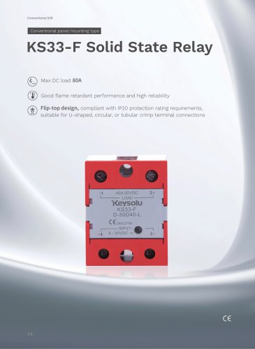
DESCRIPTION KS20 is a set of SPST-NO AC type solid state relay with small dimension, single in-line printed circuit board mounting. Using surface mount process, it is resistant to high surge current capability, suitable for electromagnetic valves, motors, incandescent control. The relay's DC input is compatible with 5VDC, 12VDC and 24VDC logic systems. Optical isolation between input and output, the output in the form of zero-cross turn-on type and random turn-on type. PRECAUTIONS 1.Soldering must be completed within 10s at 260"C or less or within 5s at 350‘C or less. 2.The SSR case serves to dissipate heat. Install the relays so that they are adequately ventilated.If poor ventilation is unavoidable, the load current must be reduced. Please refer to the curve of Max. Load Current vs Ambient Temperature. 3.The input circuitry does not incorporporate a circuit protecting the SSR from being damaged due to a reversed connection.Make sure that the polarity and the input and output are correct when connecting. 4.If the output transient voltage exceeds the nominal value, a varistor should be connected to the SSR output terminal in parallel to prevent the relay being breakdown. The recommended varistor voltage 470V. 5.When using the relay in phase control applications, at a phase control angle close to 180 degrees the relay's input signal turn off at the trailing edge of the AC sine wave must be limited to end 200ps before AC zero cross. This assures that the relay has time to switch off. Shorter times may cause loss of control at the following half cycle. 6.For the inductive load applications, the output terminal of relay should connect across a RC snubber, which can suppress the transient voltage and a voltage rising rate of exponential impact of the relay. 7.Please do not use the relay beyond the descriptions in the data sheet.lf it is a must to use it beyond descriptions, please contact Jinxinrong for more technical support.
Open the catalog to page 1
ORDERING INFORMATION Zero cross function Z:Zero cross turn-on P:Random turn-on RC snubber N: Without RC snubber Nil: With RC snubber Customer spec i a I code (242) stands for the type with different terminals layout (See the following outline dimension) OUTLINE DIMENSIONS, WIRING DIAGRAM AND PCB LAYOUT Standard Outline Dimensions PCB Layout (Bottom view)
Open the catalog to page 2
Control signal Disclaimer: This datasheet is for the customers' reference. All the specifications are subject to change without notice. Jinxinrong could not evaluate all the performance and all the parameters for every possiable application. Thus the user should be in a right position to choose the suitable product for their own application. If there is any query, please contact Jinxinrong for the technical service.However, it is the user's responsibility to determine which product should be used only. © Xiamen Jinxinrong Electronics Co., Ltd. All rights of Jinxinrong are reserved.
Open the catalog to page 3All Xiamen Jinxinrong Electronics Co., Ltd. catalogs and technical brochures


- Switching relay
- Measurement monitoring module
- DC solid state relay
- Alarm monitoring module
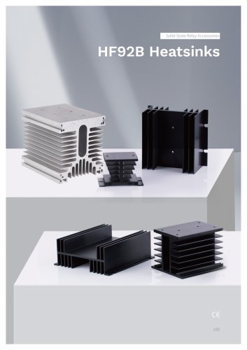
- Heatsink
- AC solid state relay
- Current monitoring module
- Single-phase solid state relay
- DIN rail solid state relay
- Printed circuit board solid state relay
- 24VDC solid state relay
- Panel-mount solid state relay
- Solid state relay with LED indicator
- DC output solid state relay
- Three-phase solid state relay
- AC output solid state relay
- Load monitoring device
- 12VDC solid state relay
- 32VDC solid state relay