- Catalogs
- Xiamen Hongfa Electroacoustic Co.,Ltd.
- HFK10-T(C32)
HFK10-T(C32)
1 /4Pages

HFK10-T(C32)
1 /4Pages
Catalog excerpts

AUTOMOTIVE RELAY Features Max.continuous current 32A(at 105℃) Extended temp. Range up to 105℃ With highly established reliability Strong resistance ability to shock & vibration Reflow soldering version available RoHS, ELV compliant Typical Applications RoHS compliant CHARACTERISTICS Contact arrangement Min.contact load Electrical load Mechanical endurance Operate time (initial)4) Release time (initial) Ambient temperature Vibration resistance (initial) Plastic sealed,Flux proofed Unit weight Notes:1) Initial value 2) The test under the follow conditions a the relay is mounted on the PCB,the coil is applied with 100% rated voltage After 200ms, the coil excitation voltage is reduced to7.8V; b The PCB is a double layer board,the thickness of the copper foil is4 oz 140 um ,the width if each copper foil is 10.64× 1±5% mm the length of the copper foil is 50 mm±1 mm,and the Tg value of the PCB is 150℃ 3) 1 min , leakage current less than 1mA. 4) The value is measured when voltage drops suddenly from nominal voltage to 0VDC and coil is not paralleled with suppression circuit. 5) When non-energized,close time of NO contacts shall not exceed 100us,when energized,opening time of closed NO contact shall not exceed 100us. 6) Since it is an environmental friendly product,please select lead-free solder when welding.The recommended soldering temperature and time is (260±3)℃,(5±0.3)s. CONTACT DATA1) Load voltage Load type Contact arrangement Load current Load current Load current Making2) Carrying2) Breaking2) On/Off ratio Electrical Ambient endurance Temperature OPS Notes:1) Load mentioned in this chart is for relays with no parallel diode or Zener Diode.For those with parallel diode,Zener Diode or other components,please contact Hongfa for more technical supports.Please also contact Hongfa if the actual application load is different from what mentioned above. All the rating are tested with opend vent hole. 2) Making 100ms,loading 800ms,breaking 100ms.
Open the catalog to page 1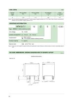
COIL DATA Notes:1) when the ambient temperature exceeds 85℃, the coil excitation voltage is required to be 13.5V, 200ms. After the relay is connected and stabilized, the coil excitation voltage is reduced to 12V. ORDERING INFORMATION Coil voltage Contact arrangement Z:1 Form C S:Plastic sealed1) Nil:Flux proofed (Reflow soldering version) Contact material Special code Notes:1) Contact is recommended for suitable condition and specifications if water cleaning or surface process is involved in assembling relays on PCB. OUTLINE DIMENSIONS, WIRING DIAGRAM AND PC BOARD LAYOUT Outline Dimensions HFK10-T-Z...
Open the catalog to page 2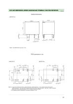
OUTLINE DIMENSIONS, WIRING DIAGRAM AND TERMINAL FUNCTION DEFINITION Notes:1) In case of no tolerance shown in outline dimension: outline dimension ≤1mm, tolerance should be ±0.2mm; outline dimension>1mm and ≤5mm,tolerance should be ±0.3mm; outline dimension>5mm and ≤30mm, tolerance should be ±0.4mm;outline dimension>30 mm, tolerance should be ±0.6mm; 2) The tolerance without indicating for PCB layout is a
Open the catalog to page 3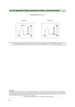
OUTLINE DIMENSIONS, WIRING DIAGRAM AND TERMINAL FUNCTION DEFINITION Wiring Diagram(Bottom view) Notes:1) Coil terminals 1# and 2# are close to load terminals 3#, 4#, 5# and 6#, to meet withstand voltage requirement of PCB, it is suggested to use PCB bonding pad 0.2mm for coil terminals 1# and 2#, and use bonding pad 0.3mm for load terminals 3# 4# and 6#. 2) Please consider to add shield between terminal 1# and 3#, 1# and 6# 2# and 4# in PCB, so as to raise the withstand voltage requirement. Disclaimer The specification is for reference only. See to "Terminology and Guidelines" for more information....
Open the catalog to page 4All Xiamen Hongfa Electroacoustic Co.,Ltd. catalogs and technical brochures
 HF5F
HF5F3 Pages
 HCAB
HCAB10 Pages
 HFA4G
HFA4G3 Pages
 HF3635
3 Pages
 HFK10-T(C16)
4 Pages
 Hongfa Automotive Electronics
15 Pages
 Film Capacitors
4 Pages
 Automation Equipment
14 Pages
 Hongfa Group Profile
18 Pages

- Junction block
- Switching relay
- Capacitor
- Sanxing Electric circuit breaker
- Screw connection terminal block
- Electromechanical relay
- DC electromechanical relay
- Contactor
- SMD capacitor
- Sanxing Electric voltage circuit breaker
- Relay module
- Plug-in terminal block
- Power relay
- Film capacitor
- Printed circuit board electromechanical relay
- Current capacitor
- Voltage capacitor
- Printed circuit board terminal block
- Cylindrical capacitor
- AC electromechanical relay