HF3635
1 /3Pages

HF3635
1 /3Pages
Catalog excerpts

CHARGER MODULE Features Max.continuous current 40A 40A switching capability @ 240VAC Extended temp. Range up to 85 With highly established reliability High space utilization RoHS, ELV compliant Typical Applications RoHS compliant On board charger,charging pile,EV Charger IC-CPD CHARACTERISTICS Contact arrangement Short circuit Max. switching voltage Min. Contact load Electrical load Mechanical endurance Insulation resistance (initial)4) Dielectric stength Surge voltage(initial) (Between coil to contact) Pollution degree Material Group Overvoltage category Operate time (initial)5) Release time (initial) Ambient temperature Flux proofed Unit weight Notes:1) Initial value, All tests are conducted under room temperature and room humidity. 2) the test under the follow conditions a the charger module is mounted on the PCB,The coil applies 100% rated voltage excitation for 200ms, then drops to holding voltage excitation b The PCB is a double layer board,the thickness of the copper foil is 4 oz 140 um ,the width if each copper foil is 13.15× 1±5% mm the length of the copper foil is 50 mm±1 mm,and the Tg value of the PCB is 150℃ 3) Comply with 2kA short circuit test using K5 40A fuse (UL2231-2 clause 33). 4) 1min , leakage current less than 1mA. 5) The value is measured when voltage drops suddenly from nominal voltage to 0VDC and coil is not paralleled with suppression circuit. Operate and release time excluding contact bounce. 6) When non-energized,close time of NO contacts shall not exceed 100us,when energized,opening time of closed NO contact shall not exceed 100us. 7) Since it is an environmental friendly product,please select lead-free solder when welding.The recommended soldering temperature and time is (260±3)℃,(5±0.3)s. 8) To avoid distortion of the terminals and the mount tabs,when tightening a screw,use flat washers,in addition,to avoid loosening of the screw,when tightening a screw,use spring washers.these will ensure there is sufficient thickness and strength to prevent distortion of the terminals and mount tabs. To avoid unexpected damage,tighten screw to within the specified torque shown below:M4 screw:1.2N~1.4N.m. HONGFA RELAY ISO9001 IATF16949 ISO14001 OHSAS18001 IECQ QC 080000 CERTIF
Open the catalog to page 1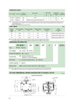
CONTACT DATA1) Load voltage Load type On/Off ratio Load current Contact arrangement Electrical Ambient endurance2) Temperature OPS Notes:1) Load mentioned in this chart is for relays with no parallel diode or Zener Diode.For those with parallel diode,Zener Diode or other components,please contact Hongfa for more technical supports.Please also contact Hongfa if the actual application load is different from what mentioned above. 2) Making 100ms,loading 800ms,breaking 100ms. COIL DATA Notes:1) To energize charger module properly apply 100%~125% nominal coil voltage for 100ms~200ms. 2) Coil holding...
Open the catalog to page 2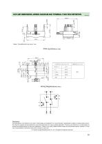
OUTLINE DIMENSIONS, WIRING DIAGRAM AND TERMINAL FUNCTION DEFINITION Wiring Diagram(Bottom view) A3 Disclaimer The specification is for reference only. See to "Terminology and Guidelines" for more information. Specifications subject to change without notice. We could not evaluate all the performance and all the parameters for every possible application. Thus the user should be in a right position to choose the suitable product for their own application. If there is any query, please contact Hongfa for the technical service. However, it is the user’s responsibility to determine which product should...
Open the catalog to page 3All Xiamen Hongfa Electroacoustic Co.,Ltd. catalogs and technical brochures
 HF5F
HF5F3 Pages
 HCAB
HCAB10 Pages
 HFA4G
HFA4G3 Pages
 HFK10-T(C16)
4 Pages
 HFK10-T(C32)
4 Pages
 Hongfa Automotive Electronics
15 Pages
 Film Capacitors
4 Pages
 Automation Equipment
14 Pages
 Hongfa Group Profile
18 Pages

- Junction block
- Switching relay
- Capacitor
- Circuit breaker
- Screw connection terminal block
- Electromechanical relay
- DC electromechanical relay
- Contactor
- SMD capacitor
- Voltage circuit breaker
- Relay module
- Plug-in terminal block
- Power relay
- Film capacitor
- Printed circuit board electromechanical relay
- Current capacitor
- Voltage capacitor
- Printed circuit board terminal block
- Cylindrical capacitor
- AC electromechanical relay