- Catalogs
- Xiamen Dexing Magnet Tech. Co., Ltd.
- User Manual of DXF2030 Current Source
User Manual of DXF2030 Current Source
1 /30Pages
User Manual of DXF2030 Current Source
1 /30Pages
Catalog excerpts

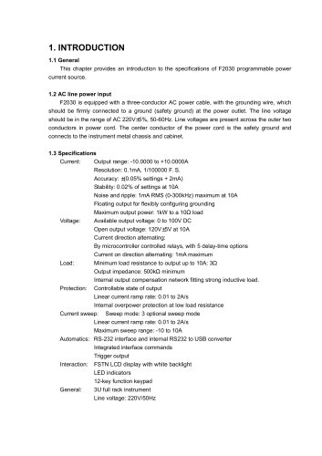
This chapter provides an introduction to the specifications of F2030 programmable power current source. F2030 is equipped with a three-conductor AC power cable, with the grounding wire, which should be firmly connected to a ground (safety ground) at the power outlet. The line voltage should be in the range of AC 220V±5%, 50-60Hz. Line voltages are present across the outer two conductors in power cord. The center conductor of the power cord is the safety ground and connects to the instrument metal chassis and cabinet. Current: Output range: -10.0000 to +10.0000A Stability: 0.02% of settings at 10A Noise and ripple: 1mA RMS (0-300kHz) maximum at 10A Floating output for flexibly configuring grounding Maximum output power: 1kW to a 10Q load Voltage: Available output voltage: 0 to 100V DC Open output voltage: 120V±5V at 10A Current direction alternating: By microcontroller controlled relays, with 5 delay-time options Current on direction alternating: 1mA maximum Load: Minimum load resistance to output up to 10A: 3Q Output impedance: 500kQ minimum Internal output compensation network fitting strong inductive load. Protection: Controllable state of output Linear current ramp rate: 0.01 to 2A/s Internal overpower protection at low load resistance Current sweep: Sweep mode: 3 optional sweep mode Linear current ramp rate: 0.01 to 2A/s Maximum sweep range: -10 to 10A Automatics: RS-232 interface and internal RS232 to USB converter Integrated interface commands Trigger output Interaction: FSTN LCD display with white backlight LED indicators 12-key function keypad General: 3U full rack instrument
Open the catalog to page 1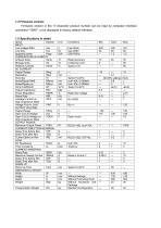
Firmware version in the 17-character product number can be read by computer interface command “*IDN?”, or be displayed in factory default interface.
Open the catalog to page 2
1.6 Safety Summary Observe the following general safety precautions during all phases of instrument operation, service, and repair. Failure to comply with these precautions or with specific warnings elsewhere in this manual violates safety standards of design, manufacture, and intended use of the instrument. We assume no liability for customer failure to comply with these requirements. The F2030 protects the operator and surrounding area from electric shock or burn, mechanical hazards, excessive temperature, and spread of fire from the instrument. Environmental conditions outside of the conditions...
Open the catalog to page 3
This Page Intentionally Left Blank.
Open the catalog to page 4
2. INSTALLATION 2.1 General This chapter provides the methods of installation and cable connection in rear panel. 2.2 Inspection and unpacking Inspect shipping containers for external damage. Make all claims for damage (apparent or concealed) or partial loss of shipment in writing to us within five (5) days from receipt of goods. If damage or loss is apparent, please notify the shipping agent immediately. Open the shipping containers. Use the packing list included with the system to verify receipt of the instrument, sensor, accessories, and manual. Inspect for damage. Inventory all components...
Open the catalog to page 5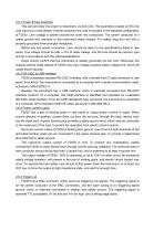
2.6.1 Power & fuse assembly This part provides line power to instrument, via line cord. The assembly includes an IEC line cord input and a fuse drawer. A three-conductor line cord is included in the standard configuration of F2030. Line voltage is present across the outer two conductors. The center conductor is a safety ground and connects to the instrument metal chassis. For safety, plug the cord into a properly grounded three-pronged receptacle. Before any line power connection, care should be taken to the specifications listed in rear panel. Line voltage should be with +/-5% of rated voltage,...
Open the catalog to page 6
This chapter covers aspects of operation: front panel controls, functions, current settings and sweeping, computer interface configuration and factory default settings. F2030 front panel includes: (1) LCD display, (2) LED indicators, (3) keyboard and (4) power switch. F2030 employs 128x64 graphic dot FSTN LCD display, with white backlight. The display region is divided according to functioning into: (1) Current setting region In standard interface, the current setting region has one row to display output current, with a fining symbol under the lowest 4 digits. In current setting interface, there...
Open the catalog to page 7
3.3 Front Panel Keyboard As mentioned before, keyboard is divided into 5 functioning regions as: (1) State control of output OUT key is to switch state of output between output state and high impedance state. (2) Current direction control +/- key is to switch current directions between positive and negative. (3) Instrument functions TRIG key is to configure trigger mode, delay time and audio of normal trigger function, and to configure trigger mode, interval and audio of sweep trigger function. MENU key is to set computer interface, baud rate of serial ports, ramp rate, sweep mode, maximum sweep...
Open the catalog to page 8
displayed. Use LEFT/RIGHT keys to select a required digit, and UP/DOWN keys to change the value of the digit. Use +/- key to change the current direction. Press ENT to confirm the setting, or press ESC to cancel. Computer interface command CUR is also used to set output current. 3.5 Linear Current Ramp 3.5.1 Time constant of inductive load F2030 is designed to drive inductive load, i.e. electromagnets, Helmholtz coil pairs and solenoids. Such loads have large inductance of L and nonzero DC resistance of R, the ratio L/R is the time constant. If the time constant is too large, the output current...
Open the catalog to page 9
back into the black binding post, vice versa. Relay reversal mechanism can produce current of totally equal amplitude, but opposite directions. It is very useful in some application, which is very sensitive to the errors of amplitude between current in different directions. 3.6.2 Reversal procedure In standard display interface, press +/- key to switch direction. In current setting interface, +/key is to change the sign of setting value, which takes effect after ENT is pressed. Relay reversal cannot be issued when output current is not zero, especially with inductive loads. Intensive reversal...
Open the catalog to page 10All Xiamen Dexing Magnet Tech. Co., Ltd. catalogs and technical brochures
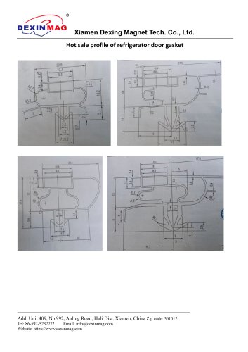 Common door gasket profile
6 Pages
 DXME-15C10 Operation manual
18 Pages
 Rubber Magnet MSDS
18 Pages
 Impulse Magnetizer ROHS
18 Pages
 Dexinmag Product Categories
32 Pages
 DX-1205F Gaussmeter
16 Pages
 Three Dimensional Hall Probe
6 Pages
 Two-dimensional Hall Probe
7 Pages
 Axial Probe
8 Pages
 Transverse Probe
12 Pages


- Cutting system
- Industrial press
- Power supply unit
- DC power supply
- Kiln
- AC/DC power supply
- Welding system
- Chamber kiln
- Hydraulic press
- Forming press
- Measuring device
- Automatic cut-off machine
- Heat treatment kiln
- Monitoring analyzer
- Knife cutting system
- Automatic welding machine
- Measuring machine
- Automatic analyser
- Microscope
- Making machine