- Catalogs
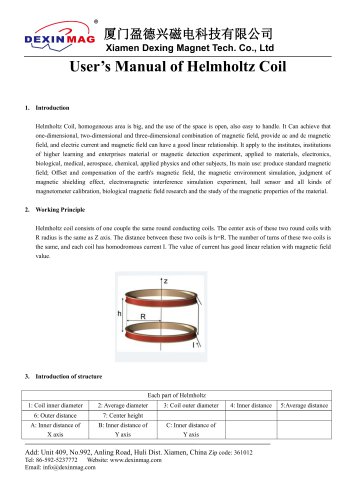
- Xiamen Dexing Magnet Tech. Co., Ltd.
- User Manual of DXF2005 Programmable Current Source
User Manual of DXF2005 Programmable Current Source
1 /62Pages

User Manual of DXF2005 Programmable Current Source
1 /62Pages
Catalog excerpts

USER MANUAL Model: DX- F2005 PROGRAMMABLE CURRENT SOURCE Xiamen Dexing Magnet Tech. Co., Ltd. Add: Unit 405,10th Factory Building of Lianfa, No.34, Yuehua Road, Huli District, Xiamen, China 361006 Tel: (86) 0592 5237772 Mobile Phone: (86) 18030236818 Website: www.dexinmag.com Email: [email protected]
Open the catalog to page 1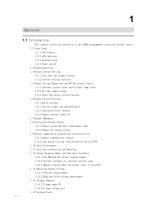
This chapter covers the operation of the F2005 programmable precision current source. 1.4 Output Current Setting 1.4.1 Fine tune the output current. 1.4.2 Current setting interface 1.5 Output Voltage Range and Load DC Resistance Limits 1.5.1 Constant current state and voltage clamp state 1.5.3 State switching critical process 1.6 Output Current Accuracy 1.6.2 Current output lag approaching 0 1.6.3 Calculated error current 1.6.4 Output current stability 1.8 Setting the Output Status 1.8.1 Output status and boot replacement load 1.8.2 Change the output status 1.9 Output compensation network and...
Open the catalog to page 2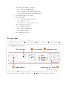
1.16 Setting the Computer Interface 1.16.1 Set the interface type 1.16.2 Set the serial interface baud rate 1.16.3 Install and set up the USB-232 port 1.17 Restoring Factory Settings 1.18 Load Example 1.18.1 Low resistance measurement 1.18.2 Inductive load 1.18.3 PN junction semiconductor device 1.19 Grounding Relationships 1.19.1 Floating output 1.19.2 Floating measurement 1.19.3 Ground relation 1.20 Keypad Menu Structure. 1.2 Front Panel The front panel of the F2005 programmable precision current source consists of four parts: LCD display、 LED indicator、 LED indicator、 Figure 3-1 F2005...
Open the catalog to page 3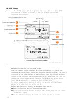
1.2.1LCD Display The F2005 uses a 128 x 64 graphic dot matrix white backlit FSTN LCD display as shown in Figure 3-2.The LCD display is divided according to function: Figure 3-2 LCD Monitor Function Areas Trim Bit Flags Anti-shock mode Current setting zone Setting zone Trigger status indication Unit Suffix Oscillation Warning Signs baud rate indication a.1-line readout for both current and clamp voltage setup areas Keyboard lock indication b. Current setup area for 2 lines of readings FIG-MAN-F2005-0017 Current Setting Area: Set the output current. Under the standard display interface,...
Open the catalog to page 4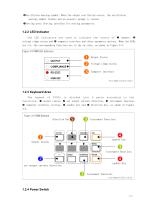
Oscillation warning symbol: When the output oscillation occurs, the oscillation warning symbol flashes and an acoustic prompt is issued. Setting area: Setting interface for setting parameters. 1.2.2 LED Indicator The LED indicators are used to indicate the status of outputs 、 voltage clamp status and computer interface and other parameter options. When the LEDs are lit, the corresponding functions are in the on state, as shown in Figure 3-3. Figure 3-3 F2005 LED Indicators Output Status Voltage clamp status Computer Interface FIG-MAN-F2005-0018 1.2.3 Keyboard Area The keypad of...
Open the catalog to page 5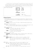
The power switch of the F2005 adopts a boat-shaped switch, and the status of the on and off position is shown in Figure 3-5. Before turning off the power, please set the output terminal state to high resistance first to avoid the impact of possible switching transients on the load and the impact of capacitive and inductive energy storage loads on the internal circuitry of the F2005. Figure 3-5 Power Switch On/Off 1.3Keypad Operation The following are definitions of the front panel keypad functions. Subsequent sections will provide detailed descriptions of the keypad operations corresponding to...
Open the catalog to page 6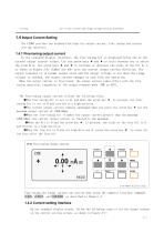
bit in the current and clamp voltage setting interface. 1.4 0utput Current Setting The F2005 provides two keyboard Settings for output current: Fine tuning and current setting interface. 1.4.1 Fine-tuning output current In the standard display interface, the fine-tuning bit is displayed below one of the current output current values. Use the arrow keys and to cycle between you to select the trim bits. Use arrow keys and to increase or decrease the value of the bit by 1, as shown in Figure 3-6. Symbol key +/- sets the current output current direction. The output terminal is in normal output...
Open the catalog to page 7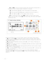
Press ENTER to enter the current setting screen. The current setting value is displayed in line 2, and the current setting bit is reversed. Use the arrow keys and rotate the Settings bit left and right. Use the arrow keys and increase or decrease the set bit value by 1. Use the symbol key +/- to set the output current direction. After setting the current, press ENTER to make the current output current change to the set value, or press ESC cancel the setting. The current value remains the previous value. 3-7 Current setting interface Follow the following rules to set the output current...
Open the catalog to page 8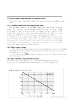
The effective output voltage VCMPL of F2005 is 45V, and the open output voltage VOPEN is about 46. 2V. When the output terminal is in the normal output state, under certain set output current IOUT, different load DC resistance RLOAD may cause the output voltage VOUT=IOUTRLOAD to reach or exceed VCMPL=40V. For example, setting 1A current to flow through a 50 resistor will result in an output voltage higher than VCMPL and an open output voltage VOPEN=46.2V, resulting in an actual output current lower than 1A. Although the output voltage slightly higher than VCMPL=40V does not significantly affect...
Open the catalog to page 9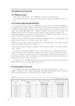
The output current accuracy of the F2005 uses a fixed error representation. In constant current state, the rated accuracy of current output is (0. 015% set value +10 As a precision current source, the F2005 boasts a step resolution of 10 u A (1/100,000 of the rated full-scale output). However, this does not imply that the output current quality of the F2005 fully meets the rated specifications when the absolute value of the output current | Iout | is less than 100pA. When |Iout| < 100 u A (1/10,000 of the rated full-scale output), the F2005 may exhibit hysteresis between the actual output current...
Open the catalog to page 10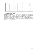
1.6.4 Output Current Stability When the ambient temperature is in the range 15—35C and constant, the typical stability of F2005 is 20ppm/h. To ensure high stability, F2005 should avoid operating in an environment with drastic temperature changes and away from high-power heat sources. In addition, since F2005 itself may generate a lot of heat during operation, in order to avoid obvious self-heating effect, sufficient heat dissi
Open the catalog to page 11All Xiamen Dexing Magnet Tech. Co., Ltd. catalogs and technical brochures
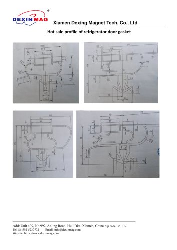 Common door gasket profile
6 Pages
 DXME-15C10 Operation manual
18 Pages
 Rubber Magnet MSDS
18 Pages
 Impulse Magnetizer ROHS
18 Pages
 Dexinmag Product Categories
32 Pages
 DX-1205F Gaussmeter
16 Pages
 Three Dimensional Hall Probe
6 Pages
 Two-dimensional Hall Probe
7 Pages
 Axial Probe
8 Pages
 Transverse Probe
12 Pages


- Cutting system
- Industrial press
- Power supply unit
- DC power supply
- Kiln
- AC/DC power supply
- Welding system
- Chamber kiln
- Hydraulic press
- Forming press
- Measuring device
- Automatic cut-off machine
- Heat treatment kiln
- Monitoring analyzer
- Knife cutting system
- Automatic welding machine
- Measuring machine
- Automatic analyser
- Microscope
- Making machine