- Catalogs
- Xiamen Dexing Magnet Tech. Co., Ltd.
- User Manual of DX-FE2000 Ferroelectric Analyzer
User Manual of DX-FE2000 Ferroelectric Analyzer
1 /27Pages

User Manual of DX-FE2000 Ferroelectric Analyzer
1 /27Pages
Catalog excerpts
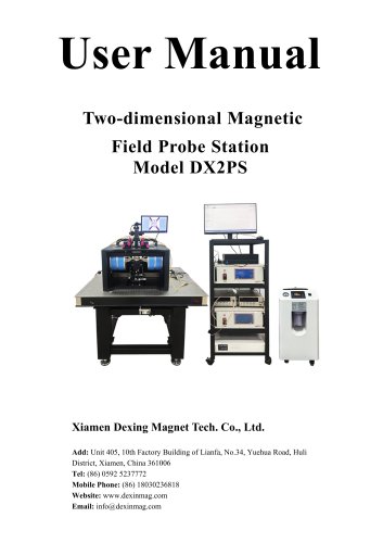
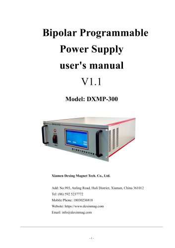
User Manual Ferroelectric Analyzer Model DX-FE2000 Xiamen Dexing Magnet Tech. Co., Ltd. Add: Unit 409, 4/F, No.992, Anling Road, Huli District, Xiamen, China Tel: (86) 0592 5237772 Mobile Phone: (86) 18030236818 Website: www.dexinmag.com Email: [email protected]
Open the catalog to page 1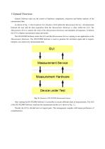
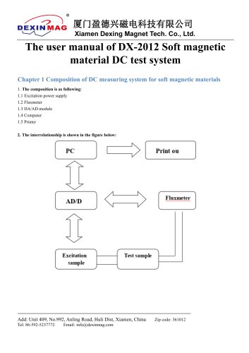
General Software tasks are the control of hardware components, extraction and further analysis of the measurement data. As shown in Fig. 1.1 the Graphical User Interface (GUI) pilots the Measurement Service. All interactions between the user and the data acquisition from the Measurement Hardware is done within the GUI. The Measurement Service controls the work of the Measurement Hardware and interprets all responses. It informs the GUI to display measurement status and results. The DX-FE2000 Software unites the GUI and the Measurement Service running as one application on the Measurement Hardware....
Open the catalog to page 3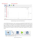
Input parameters Data Visualization Fig. 1.2: Main program window of the DX-FE2000 Software The DX-FE2000 software performs a variety of measurements including DHM, PZM, BDM, POM, PM, CVM, LM. By clicking on the “Select Project” tab and selecting the desired test type from the test item types that appear. By clicking on the “Setting” tab, you can adjust the counting parameters in the pop-up parameter settings screen. Notice that every time you modify a parameter, you must click the “Save Parameters” option to save the operation, the set parameter can take effect. The High Voltage Amplification...
Open the catalog to page 4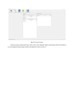
Check any basic measurement type, click on the “select filepath” button at the bottom left of the software, you can change the data storage location, the dialog box shown in Fig 1.3.
Open the catalog to page 5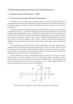
2 Measurement program introduction and software description 2.1 Dynamic Hysteresis Measurement – DHM 2.1.1 Measurement procedure and typical measurement The DHM records the hysteresis loop of a ferroelectric material and assists to examine the influence of process parameters on the shape of the hysteresis loop. Measurement parameters like amplitude or frequency of the excitation signal can be varied. The software extracts the characteristic values like Pr, Vc etc. from the hysteresis loop. Typically an excitation signal needs to be generated to record the hysteresis return line, such as the triangle...
Open the catalog to page 6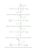
Fig. 2.2 Polarization vs. Voltage graph of a Dynamic Hysteresis Measurement without prepolarization Fig. 2.3 Polarization vs. Voltage graph of a single loop Dynamic Hysteresis Measurement with prepolarization Fig. 2.4 Polarization vs. Voltage graph of a single loop Dynamic Hysteresis Measurement without prepolarization Fig. 2.5 Polarization vs. Voltage graph of a unipolar, single loop Dynamic Hysteresis Measurement with prepolarization
Open the catalog to page 7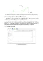
Fig. 2.6 Polarization vs. Voltage graph of a unipolar, single loop Dynamic Hysteresis Measurement without prepolarization 2.1.2 Executing a Dynamic Hysteresis Measurement Click DHM in the “Select Project” dialog box of DX-FE2000 software, adjust the parameters and click “Save Parameters”, then press “Run” button to execute DHM measurement. The DX-FE2000 software allows the monitoring of different types of measurements during the measurement process. Select the type of measurement to be monitored by clicking on the “DHM”, “Excitation Response”, “IV”, “Nomeclature of characteristic” tab in the...
Open the catalog to page 8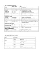
Table 2.1: Input Test Parameters
Open the catalog to page 9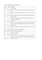
Table 2.3: Nomenclature of characteristic values
Open the catalog to page 10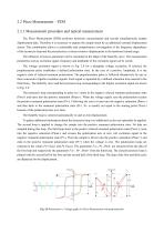
2.2 Piezo Measurement – PZM 2.2.1 Measurement procedure and typical measurement The Piezo Measurement (PZM) performs hysteresis measurements and records simultaneously sample displacement data. Therefore it is necessary to capture the sample strain by an additional external displacement sensor. This combination allows a comfortable and comprehensive investigation of the frequency dependence of the hysteresis loop and the piezoelectric or electro strictive displacement in the hardware limited range. The influence of process parameter can be examined on the shape of the butterfly curve. The measurement...
Open the catalog to page 11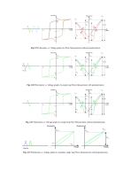
Fig. 2.9 Polarization vs. Voltage graph of a Piezo Measurement without prepolarization Fig. 2.10 Polarization vs. Voltage graph of a single loop Piezo Measurement with prepolarization Fig. 2.11 Polarization vs. Voltage graph of a single loop Piezo Measurement without prepolarization Fig. 2.12 Polarization vs. Voltage graph of a unipolar, single loop Piezo Measurement with prepolarization
Open the catalog to page 12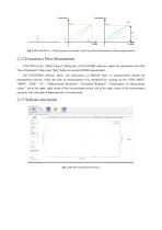
Fig. 2.13 Polarization vs. Voltage graph of a unipolar, single loop Piezo Measurement without prepolarization 2.2.2 Execution a Piezo Measurement Click PZM in the “Select Project” dialog box of DX-FE2000 software, adjust the parameters and click “Save Parameters”, then press “Run” button to execute PZMM measurement. The DX-FE2000 software allows the monitoring of different types of measurements during the measurement process. Select the type of measurement to be monitored by clicking on the “PZM_DHM”, “DHM”, “PZM”, “IV”, “Displacement Waveform”, “Excitation Response” “Nomeclature of characteristic...
Open the catalog to page 13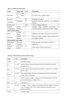
Table 2.4: Input Test Parameters
Open the catalog to page 14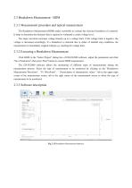
2.3 Breakdown Measurement - BDM 2.3.1 Measurement procedure and typical measurement The Breakdown Measurement (BDM) makes it possible to evaluate the electrical insulation of a material. It helps to determine the thickness that is required to withstand a certain voltage level. The slope waveform increases voltage linearly up to a voltage limit; if the voltage limit is negative, the voltage is decreased accordingly. If a breakdown is detected due to either of enabled stop conditions, the measurement is immediately stopped without e.g. reaching the voltage limit. 2.3.2 Executing a Breakdown Measurement...
Open the catalog to page 16
Table 2.7: Input Test Parameters
Open the catalog to page 17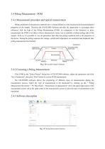
2.4 Poling Measurement - POM 2.4.1 Measurement procedure and typical measurement Poling conditions of piezoelectric materials have a strong influence on the electrical and electromechanical properties of the sample. Therefore the DX-FE2000 Software provides the opportunity to investigate these influences with the help of the Poling Measurement (POM). In comparison to the hysteresis or piezo measurement the POM is not able to derive characteristic values, but to establish a defined poling state of the sample. To do so, it is possible to vary all parameters that effect the poling conditions and...
Open the catalog to page 18All Xiamen Dexing Magnet Tech. Co., Ltd. catalogs and technical brochures
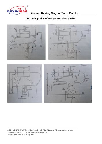 Common door gasket profile
6 Pages
 DXME-15C10 Operation manual
18 Pages
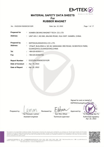 Rubber Magnet MSDS
18 Pages
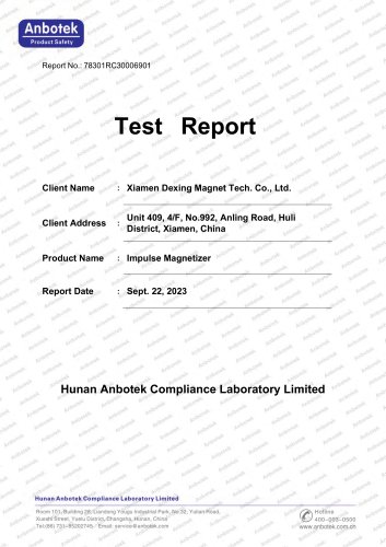 Impulse Magnetizer ROHS
18 Pages
 Dexinmag Product Categories
32 Pages
 DX-1205F Gaussmeter
16 Pages
 Three Dimensional Hall Probe
6 Pages
 Two-dimensional Hall Probe
7 Pages
 Axial Probe
8 Pages
 Transverse Probe
12 Pages
- Cutting system
- Industrial press
- Power supply unit
- DC power supply
- Kiln
- AC/DC power supply
- Welding system
- Chamber kiln
- Hydraulic press
- Forming press
- Measuring device
- Automatic cut-off machine
- Heat treatment kiln
- Monitoring analyzer
- Knife cutting system
- Automatic welding machine
- Measuring machine
- Automatic analyser
- Microscope
- Making machine