- Catalogs
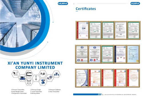
- Xi'an Yunyi Instrument Co., Ltd.
- YUNYI Gas Turbine Flowmeter
- Company
- Products
- Catalogs
- News & Trends
- Exhibitions
YUNYI Gas Turbine Flowmeter
1 /18Pages

YUNYI Gas Turbine Flowmeter
1 /18Pages
Catalog excerpts

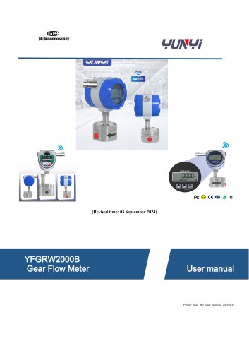
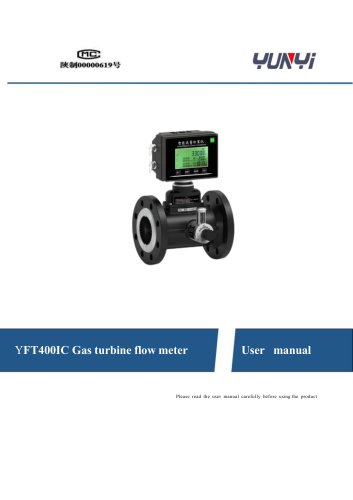
YFT400 Gas turbine flow meter User manual Please read the user manual carefully before using the product
Open the catalog to page 1
The LWQ gas turbine flow meter is a precision measuring instrument with high precision and high reliability.Suitable for all kinds of single-phase gas measurement, used in the city gas, petroleum , chemical,electric power, metallurgy and other industries gas measurement. LWQ gas turbine flow meter has excellent low pressure and high pressure metering performance, suitable for measuring accurate measurement of large flow gas. According to the user needs,our company can provide different accuracy levels, different performance of the turbine flow meter. 2. leading feature ◆ High accuracy, good repeatability,...
Open the catalog to page 3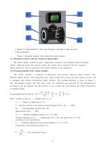
1: Display 2: volume modifier 3: flow meter housing 4: oil pump 5: output air insert 6: front guide fluid Figure 1. Schematic diagram of the turbine flow meter structure 3.2. Mechanical counter with low-frequency signal output The turbine rotates , reduced by gears , magnetically coupled to the mechanical head. The digital wheel is displayed as the total working volume , the counter can be equipped with low signal output unit , can be connected to the volume modifier or user equipment. 3.3. Working principle of the volume modifier The volume modifier is composed of temperature and pressure detection...
Open the catalog to page 4
(For natural gas compression factor, calculated according to CNPC NX-19 standard); Zn-is the gas compression coefficient under the standard stat Zg-is the gas compression coefficient in the working state. A. WT series gas turbine flow meter performs JJG1037-2008 Turbine flowmeter verification procedure B. Implement Q / WD 003-2020 WTEI Gas Turbine Flowmeter enterprise standard Implement Q / WD 0052020 WTD Gas Turbine Flowmeter enterprise standard C. Implement GB / T18940-2003 / ISO995 1: 1993 National standard for measuring turbine Flow meters in closed pipeline D. Implement GB / T28848-2012...
Open the catalog to page 5
◆ Pulse signal (three-line system) : the pulse signal detected by the flow sensor is directly amplified and output through optical coupling isolation , and the maximum amplitude value is about (V -2) V (V V outside the external power supply) , the transmission distance is 50m , and operated by the external power supply. ◆ (4~20) mA standard analog signal: (4~20) mA standard analog signal linearly corresponds to (O ~ Qmax) m3 / h standard volume flow , the flow range can be set according to the parameters in the instrument , the transmission distance is 200m , the wiring mode is two or three wire...
Open the catalog to page 6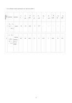
4.3.6 Product safety parameters are shown in Table 1 power supply
Open the catalog to page 7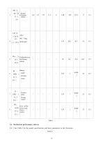
PLo 、V- Calibration/pu J2 3 _ lse/Chong output 、J2-4) 、 Battery under GND ( pressure J3_ 3 、 alarm J3-1) BJ Certain pulse Chong output Flow onThe GND lower limit Police J3(4_ output 、J3-1) Table 1 4.4. Mechanical performance indexes 4.4. 1 See Table 2 for the model specifications and basic parameters in t
Open the catalog to page 8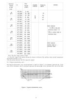
impeller material stainless steel Shell material: Carbon steel or stainless steel Shell material: Note: The flow range listed in Table ① is the flow range of the product during the factory verification (the medium under normal temperature and normal pressure is air) ; ② As the pressure increases , the flow range also expands . 4.4 .2 Typical characteristic curve The typical characteristic curve of the flowmeter is shown in Figure 3. Y coordinate represents the basic error of the instrument , and X coordinate represents the percentage of the maximum flow rate of the meter . (%) 3
Open the catalog to page 9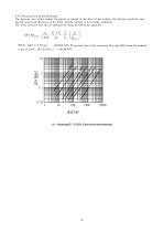
4.4 .3 Pressure loss of the flowmeter The pressure loss of the turbine flowmeter is related to the drive of the turbine , the friction inside the pipe and the speed and direction of the fluid , and the turbine is in working conditions The lower pressure loss can be obtained by using the following equation: Where: under Δ P Q max— — standard state, the pressure loss of the maximum flow rate (kPa) when the medium is dry air (20℃, 101.325 kPa, ρ = 1.205 kg/m3);
Open the catalog to page 10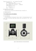
Dielectric density (kg/ m 3) ; Pa —— local The gauge pressure of Pg —— (kPa); P 0 — — Standard atmospheric pressure ( 1 0 1 . 3 2 5 kPa) ; Absolute temperature ( 2 9 3 . 1 5 K ) in the T0 — — standard state; Absolute temperature (273. 15+t) K; Q —— operating flow (m 3 / h) ; Qmax —— instrument (m 3 / h). 4.5. Explosion-proof type and grade Explosion-proof type of flowmeter: the explosion-proof grade is Exib Ⅱ BT 3 Gb. 4.6. Protection grade: IP 65 5. Overall dimensions and installation 5.1. Overall dimensions The external dimension of the flowmeter is shown in Figure 5 . The indicated dimensions...
Open the catalog to page 11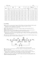
♦ There shall be no strong external magnetic field interference and strong mechanical vibration around the flowmeter. Before installation, the environmental conditions should be reviewed according to the use requirements for normal use. ♦ Flow meter should not be used in the flow of frequent changes and strong pulsation flow or pressure pulsation occasions. ♦ When the flow meter is installed outdoors, the upper part should be covered to prevent the rain immersion and the scorching sun and affecting the service life of the flow meter. ♦ The flowmeter is suitable for horizontal installation, and...
Open the catalog to page 12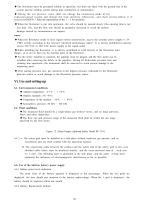
◆ The flowmeter must be grounded reliably as specified , but shall not share with the ground line of the system and the welding system during pipe installation or maintenance . ◆ Du ri ng th e use pro c e s s , use rs sha ll not cha nge the conne c ti on mode of the ex p l o s i o n - p r o o f sy s t e m an d ch a n g e th e le a d in t e r f a c e ar b i t r a r i l y , an d sh a l l st r i c tl y fol low it if nec es sa ry GB3836.1 Relevant requirements of the 1 ~ 2 for operation. ◆ When the flowmeter is put into operation , the valve should be opened slowly (the opening time is not less than...
Open the catalog to page 13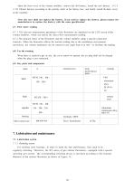
Open the front cover of the volume modifier, remove the old battery, install the new battery (12 # 3. 6V lithium battery) according to the polarity mark in the battery box, and finally install the back cover of the modifier. 6.7. 1 The relevant measurement parameters of the flowmeter are displayed on the LCD screen of the volume modifier, which can realize the direct flow measurement reading. 6.7 .2 The primary meter of the flowmeter and the volume modifier adopt a special connection structure. When the flowmeter affects the normal reading due to the installation environment restrictions, the...
Open the catalog to page 14All Xi'an Yunyi Instrument Co., Ltd. catalogs and technical brochures
 YUNYI Circular Gear Flowmeter
15 Pages
 K series
3 Pages
 YX-2006B
2 Pages
 XY-2002
1 Page
 YFM4800E
14 Pages
 YD32
YD322 Pages
 Temperature calibrator WT
2 Pages
 Pt100 temperature sensor
3 Pages
 Digital density meter JL-T
6 Pages
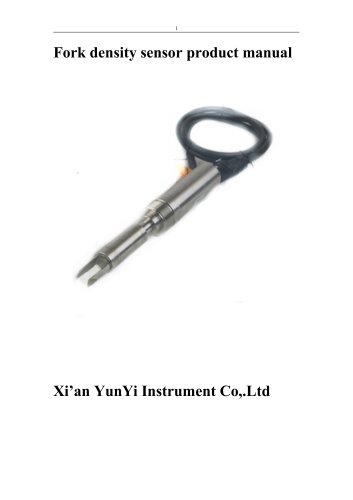 Process density sensor
8 Pages
 Digital density meter YMF883
4 Pages
 Digital density meter JL-YT
4 Pages
 Digital density meter JL-LD
2 Pages
 Digital density meter JL-SD
2 Pages
 Digital density meter JL-GD
2 Pages
 Portable pH meter K series
2 Pages
 Leak calibrator XY-2006B
2 Pages
 Deadweight tester JY
2 Pages
 Pressure calibrator XY-2001A
2 Pages
 Pressure calibrator YX-60
2 Pages
 Leak calibrator YX-2001C
2 Pages
 Dial pressure gauge YK-M4
2 Pages
 Infrared flow meter YFM-4800
21 Pages
 Mass flow meter YFU2000-B
4 Pages
 Mass flow meter Coriolis
14 Pages
 Orifice flow meter
6 Pages
 Mass flow meter MF4000
3 Pages
 Mass flow meter
3 Pages
 Vortex flow meter YFV
20 Pages
 Ultrasonic flow meter YFU2000H
14 Pages
 Turbine flow meter YFT
13 Pages
 Mass flow meter YFV300
20 Pages
 Mass flow meter YFT300D
13 Pages
 Turbine flow meter
13 Pages
 Mass flow meter MF5700
3 Pages
 Level measuring instrument
11 Pages
 Liquids level gauge YLR68
12 Pages
 Liquids level gauge
3 Pages
 Radar level sensor
12 Pages
 Diaphragm pressure switch
2 Pages
 Digital pressure controller
2 Pages
 YD31 series
4 Pages


- Kiln
- Temperature probe
- Volume flow monitor
- Liquid flow monitor
- Resistance temperature sensor
- Pressure transmitter
- Pressure gauge
- Calibration system
- Waterproof flow meter
- Analog pressure transmitter
- Gas flow monitor
- Level probe
- Digital temperature control
- Stainless steel flow monitor
- Liquid level sensor
- Pressure switch
- Industrial flow monitor
- Analog pressure gauge
- Precision flow meter