
- Catalogs
- Xi'an Yunyi Instrument Co., Ltd.
- Turbine flow meter


- Company
- Products
- Catalogs
- News & Trends
- Exhibitions
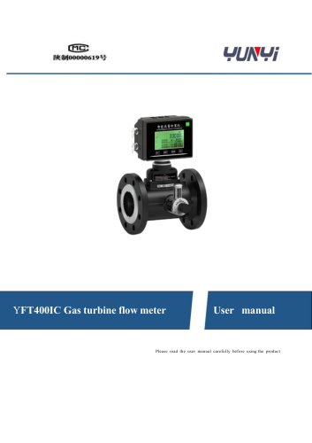
Turbine flow meter

Turbine flow meter
This document provides comprehensive instructions for the installation, use, and maintenance of YUN YI series turbine flow meters, emphasizing safety precautions, especially with hazardous or flammable liquids. The flow meters are noted for their high accuracy, repeatability, and ease of installation and maintenance.
The turbine flow meters are designed for unidirectional flow, indicated by an arrow on the body. They have a protection level of IP65 and repeatability of ±0.2%. The standard accuracy is ±1% of reading, with an optional accuracy of ±0.5%. They can handle fluid temperatures from -20°C to +110°C and pressures from 86 to 106 KPa. Available in materials like 304 and 316 stainless steel, they offer explosion-proof configurations.
Proper installation is crucial for accuracy. The document outlines necessary lengths of straight pipe runs upstream and downstream of the meter, guidance on mounting positions and orientations, and the use of flanges and threads for connections. It emphasizes preventing cavitation and ensuring proper sealing to avoid leaks.
A detailed model selection guide specifies options for power supply, output types, and materials. It includes a function table for intelligent display types and terminal configurations for various output options, including pulse and 4-20mA outputs.
Warnings include risks of electrical hazards and the importance of not removing cover plates when powered. Handling the rotor carefully to avoid damage and recommending annual calibration for optimal performance are advised.
The document outlines the functions of buttons like 'Enter', '→', '↑', and 'Esc' for navigating menus and modifying settings.
Passwords such as '1234' and '5555' are used for modifying parameters and resetting total rates. Menu parameters include settings for flow units, damp time, max and min flow rates, frequency output, density, pulse output, and communication settings.
Users can select from various flow units such as M3/h, L/h, US Gal/min, etc., and input values for parameters like damp time, max flow rate, and density.
This factory-specific section involves inputting corrected frequencies and coefficient errors for multiple points on the flow curve.
Common issues like inaccurate measurements and LCD display abnormalities are addressed with probable causes and solutions, such as cleaning the turbine or checking power supply connections.
The product comes with a one-year warranty covering defects in materials and workmanship. The process for returning defective products and obtaining a Returned Material Authorization (RMA) is detailed.
Instructions for non-warranty repairs or calibrations are provided, including the need for a purchase order number, model and serial number, and specific repair instructions.
Catalog excerpts

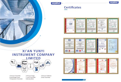
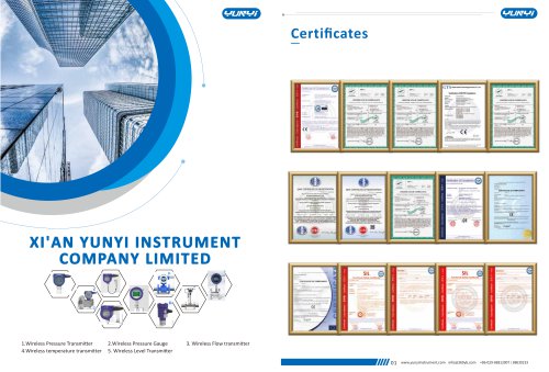
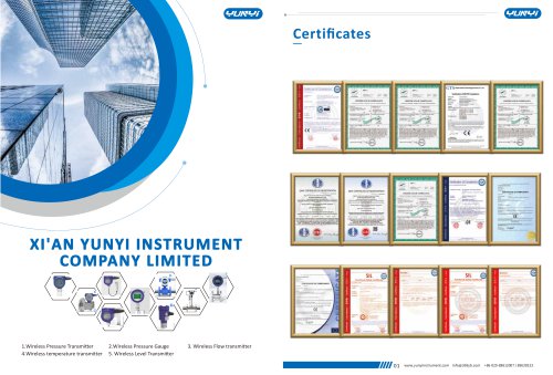
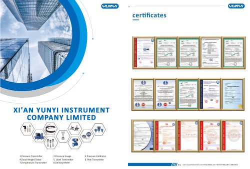
XI'AN YUNYI INSTRUMENT COMPANY LIMITED 1.Pressure Transmi�er 4.Dead Weight Tester 7.Temperature Transmi�er 2.Pressure Guage 5. Level Transmi�er 8.Density Meter
Open the catalog to page 1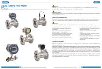
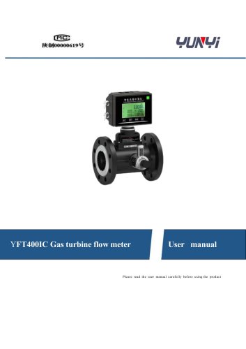
Liquid Turbine Flow Meter User Manual Warning When the flow meter is installed at explosion hazard field, DON’T remove the COVERPLATE when the meter is powered. Please make parameter se�ng at safe filed prior to installa�on. Special No�ces Pictures & Descrip�ons are for your informa�on only, please refer to the actual product. Parameters are subjected to changes without no�ce. GENERAL INFORMATION This manual will assist you in installing, using and maintaining your turbine flow meter. It is your responsibility to make that all operators have access to adequate instruc�ons about safe opera�ng and...
Open the catalog to page 2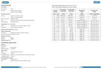
Measurable Flow Rate Range and Pres Level: (See table 1) Table 1. Measurable Flow Rage Range and Pressure Rating Standard - 304 Stainless Steel Optional - 316 Stainless Steel Tungsten Carbide Standard - 2Cr13 Stainless Steel (Optional Alloy CD4Mcu) 316 Stainless Steel Power Supply: Sensor: Transmitter: Field Display Type B: Field Display Type C: Accuracy: Standard: ±1% of reading; Wetted Components Housing: Bearings and Shaft: Rotor: Retaining Rings: Output Signal: (Where applicable) Sensor: Pulse signal (Low Level: <0.8V; High Level: >8V) Transmitter: 4 to 20 mA DC current signal Signal Transmission...
Open the catalog to page 3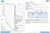
Model Selection Nominal diameter(mm) Meter material Impeller material Explosion-proof grade CAUTIONS FOR INSTALLATION Mounting Positions Turbine flow meters should be installed at the place in compliance with the requirements below: •Easy maintenance •No vibration •No electromagnetic interface •Away from heat source Mounting Orientation All turbine flow meters are designed to measure flow in only one direction. The direction is indicated by the arrow on the body. Required Lengths of Straight Runs Flow altering device such as elbows, valves and reducers can affect accuracy. See diagram 1 for typical...
Open the catalog to page 4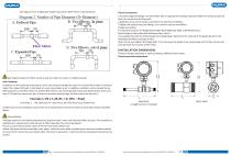
See diagram 2 for straight pipe length requirement when there is altering device. Thread Connec�ons 1.To protect against leakage, seal all threads with an appropriate sealing compound. Make the sealing compound does not intrude into the flow path. 2.Make the arrow on the outlet is pointed in the direc�on of theflow. 3.Tighten the turbine onto the fi�ngs. Use a wrench only on wrenchflats. Flange Connec�ons For standard product, the flange follows GB/T 9119-2000 (ISO 7005-1) RF (Raised Face). Note: flange can be customized following other criteria. Use a gasket between the meter flange and ma�ng flange....
Open the catalog to page 5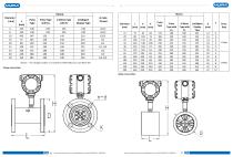
Notice: The straight section is included for DN4-DN10, but not DN15-DN Flange connection Wafer Connection
Open the catalog to page 6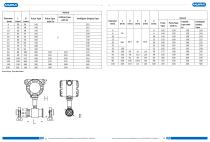
Sanitary Connection
Open the catalog to page 7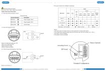
•4.Function table for the Intelligent displaytype Warning: Electrical Hazard Disconnect power before beginning installation. Turbine Flow Sensor/Transmitter • 1. Pulse Type without Explosion Proof Terminal wiring Main Power Description of the symbols: + Default Function O Optional • 2. Pulse with Explosion Proof: Notice: l.The pulse means the signal which is in direct proportion to the impeller speed. 2.The scaled Pulse means the signal when the flow rate reach ONE unit volume( m3, L, 0.01L...) 3.The batter model is ER34615 4.The battery model is ER26500 Notice: (1) High level amplitude >22V...
Open the catalog to page 8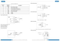
Terminal Configuration Pulse / Scaled Pulse output Notice: The communication format is Modbus-RTU protocol 220Vac powered type Grounding Switch Terminal Configuration
Open the catalog to page 9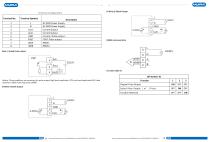
Terminal Configuration Pulse / Scaled Pulse output
Open the catalog to page 10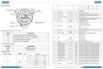
There are four keys: "Enter", "^", "t", "Esc". Description of Password Grade
Open the catalog to page 11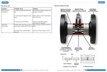
METER CONSTRUCTION Symptom Measurement is not accurate Probable Cause Solution 1. Turbine operated below minimum rate. Increase flow rate. Refer to Section 3.0 Operation Conditions Materials of Housing Stainless Steel 304 • Others available on request) Magnetic Pickup End Fittings: For hazardous areas, pickup colls supplied with explosion proof boss. Carbide Steel (Others available on request) 2. Turbine partially clogged with dried liquid Remove turbine. Clean carefully. Make rotor spins freely. 3. Installed too close to fiffings. Install correctly. Refer to Section 5.0 Cautions for Installation...
Open the catalog to page 12
METER CONSTRUCTION Hereby provides a limited warranty against defects in materials and workmanship. This product includes a one-year warranty. The warranty period shall begin on the date of the original new equipment purchase. Warrantor's obliga�on hereunder shall be limited to repairing defec�ve workmanship or replacing or repairing any defec�ve parts. In the event Purchaser believes the product is defec�ve, the product must be returned to, transporta�on prepaid by Purchaser,within the appropriate warranty period rela�ve to the product. If 's inspec�on determines the workmanship or materials...
Open the catalog to page 13All Xi'an Yunyi Instrument Co., Ltd. catalogs and technical brochures
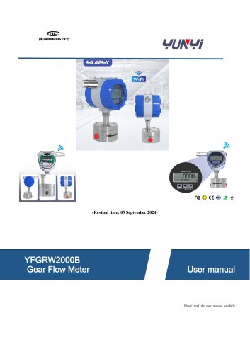 YUNYI Circular Gear Flowmeter
15 Pages
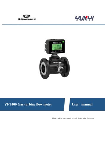 YUNYI Gas Turbine Flowmeter
18 Pages
 K series
3 Pages
 YX-2006B
2 Pages
 XY-2002
1 Page
 YFM4800E
14 Pages
 YD32
YD322 Pages
 Temperature calibrator WT
2 Pages
 Pt100 temperature sensor
3 Pages
 Digital density meter JL-T
6 Pages
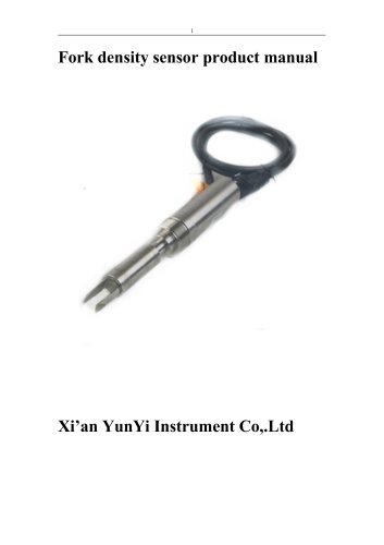 Process density sensor
8 Pages
 Digital density meter YMF883
4 Pages
 Digital density meter JL-YT
4 Pages
 Digital density meter JL-LD
2 Pages
 Digital density meter JL-SD
2 Pages
 Digital density meter JL-GD
2 Pages
 Portable pH meter K series
2 Pages
 Leak calibrator XY-2006B
2 Pages
 Deadweight tester JY
2 Pages
 Pressure calibrator XY-2001A
2 Pages
 Pressure calibrator YX-60
2 Pages
 Leak calibrator YX-2001C
2 Pages
 Dial pressure gauge YK-M4
2 Pages
 Infrared flow meter YFM-4800
21 Pages
 Mass flow meter YFU2000-B
4 Pages
 Mass flow meter Coriolis
14 Pages
 Orifice flow meter
6 Pages
 Mass flow meter MF4000
3 Pages
 Mass flow meter
3 Pages
 Vortex flow meter YFV
20 Pages
 Ultrasonic flow meter YFU2000H
14 Pages
 Turbine flow meter YFT
13 Pages
 Mass flow meter YFV300
20 Pages
 Mass flow meter YFT300D
13 Pages
 Mass flow meter MF5700
3 Pages
 Level measuring instrument
11 Pages
 Liquids level gauge YLR68
12 Pages
 Liquids level gauge
3 Pages
 Radar level sensor
12 Pages
 Diaphragm pressure switch
2 Pages
 Digital pressure controller
2 Pages
 YD31 series
4 Pages










- Kiln
- Temperature probe
- Volume flow monitor
- Liquid flow monitor
- Resistance temperature sensor
- Pressure transmitter
- Pressure gauge
- Calibration system
- Analog pressure transmitter
- Waterproof flow meter
- Gas flow monitor
- Level probe
- Digital temperature control
- Stainless steel flow monitor
- Liquid level sensor
- Pressure switch
- Industrial flow monitor
- Analog pressure gauge
- Waterproof pressure transmitter