
- Catalogs
- Xi'an Yunyi Instrument Co., Ltd.
- Orifice flow meter


- Company
- Products
- Catalogs
- News & Trends
- Exhibitions
Orifice flow meter

Orifice flow meter
qm = C/(1-β4)0.5 × ξ × π/4 × d2 (2△Pρ1)0.5
qv = C/(1-β4)0.5 × ξ × π/4 × d2 (2△P/ρ1)0.5
Where qm is mass flow, qv is volume flow, C is the outflow coefficient, ξ is the inflation coefficient, d is the throttle device diameter, △P is the differential pressure, and ρ is the fluid density.
Catalog excerpts

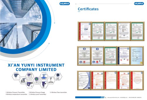
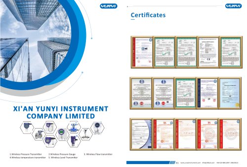
XI'AN YUNYI INSTRUMENT CO.,LTD. 1.Pressure Transmi�er 4.Dead Weight Tester 7.Temperature Transmi�er 2.Pressure Gauge 5. Level Transmi�er 8.Density Meter 3.Pressure Calibrator 6.Flow Transmi�er https://www.yunyiinstrume
Open the catalog to page 1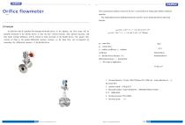
Orifice flowmeter This measurement method is based on the law of conservation of energy and mobility continuity equation. The relationship between differential pressure and flow can be determined by the following formula: Principle As fluid flow full of a pipeline flow through the throttle device in the pipeline, the flow beam will be partially contracted in the throttle device so that the flow velocity increase, static pressure decrease, and then Static pressure difference will be formed in front and back of the throttle device. The greater flow velocity of fluid is, the greater differential...
Open the catalog to page 2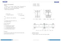
1. Corner taps. (Figure 1) 2. Flange taps. (Figure 2) conditions change, will occur. Therefore, to allow, (flow coefficient for the constant) the measurement can be corrected with the following formula. 1. Changes of Pressure and temperature unit) Q1—reading flow (volume unit)(volume unit) R1—the designed weight of flow material R2—the actual weight flow material 2. Change of Pipe diameter 3. G2= G1α2ε2 /α1ε1 α 1 — The original design flow coefficient α 2 — The actual design flow coefficient ε 1 — The original design inflation coefficient ε 2—The actual design inflation coefficient 4. maintenance...
Open the catalog to page 3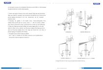
axis and gasket concentric, the misalignment should not exceed 0.002D / β. After clamping the gasket should not be into the internal pipeline. 2. Positive and negative direction of the orifice, upstream flange taps and downstream flange taps should be coincident with the direction of the dielectric flow. Position of the pressure tapping is determined by the flow characteristics and the transmitter installation status. 3. Connecting the pipeline to the throttle device, the non-orthogonality of the welding section and the pipe axis can not exceed 1 º. After the internal welding seam should be processed...
Open the catalog to page 4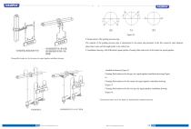
Figure IV 8. Requirement of the guiding pressure pipe. The material of the guiding pressure pipe is determined by the nature and parameter of the flow material, inner diameter larger than 6 mm, and the length prefer to be within 16m. 9. Installation drawing of the differential signal pipeline Cleaning fluid under test for the liquid, the signal pipeline Cleaning fluid under test for the steam, the signal pipeline installation drawing installation drawing (Figure 5) Cleaning fluid under test for the gas, the signal pipeline installation drawing (Figure 6) Cleaning fluid under test for the steam,...
Open the catalog to page 5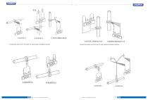
Cleaning fluid under test for the liquid, the signal pipeline installation drawing Cleaning fluid under test for the gas, the signal pipeline installation drawing
Open the catalog to page 6All Xi'an Yunyi Instrument Co., Ltd. catalogs and technical brochures
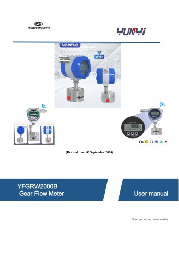 YUNYI Circular Gear Flowmeter
15 Pages
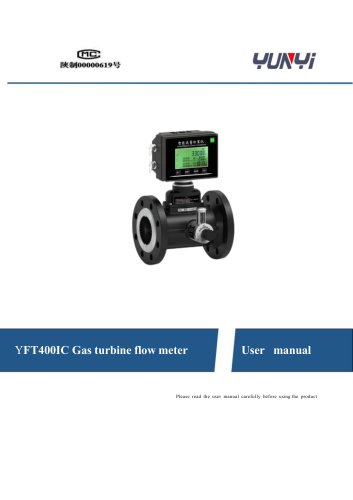
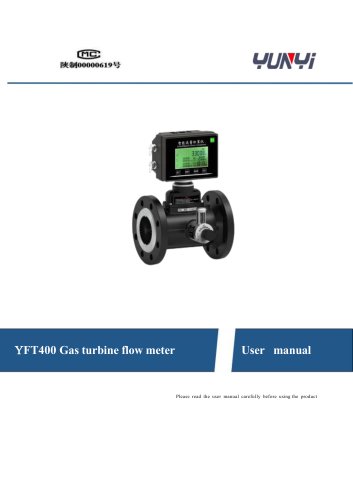 YUNYI Gas Turbine Flowmeter
18 Pages
 K series
3 Pages
 YX-2006B
2 Pages
 XY-2002
1 Page
 YFM4800E
14 Pages
 YD32
YD322 Pages
 Temperature calibrator WT
2 Pages
 Pt100 temperature sensor
3 Pages
 Digital density meter JL-T
6 Pages
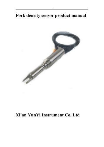 Process density sensor
8 Pages
 Digital density meter YMF883
4 Pages
 Digital density meter JL-YT
4 Pages
 Digital density meter JL-LD
2 Pages
 Digital density meter JL-SD
2 Pages
 Digital density meter JL-GD
2 Pages
 Portable pH meter K series
2 Pages
 Leak calibrator XY-2006B
2 Pages
 Deadweight tester JY
2 Pages
 Pressure calibrator XY-2001A
2 Pages
 Pressure calibrator YX-60
2 Pages
 Leak calibrator YX-2001C
2 Pages
 Dial pressure gauge YK-M4
2 Pages
 Infrared flow meter YFM-4800
21 Pages
 Mass flow meter YFU2000-B
4 Pages
 Mass flow meter Coriolis
14 Pages
 Mass flow meter MF4000
3 Pages
 Mass flow meter
3 Pages
 Vortex flow meter YFV
20 Pages
 Ultrasonic flow meter YFU2000H
14 Pages
 Turbine flow meter YFT
13 Pages
 Mass flow meter YFV300
20 Pages
 Mass flow meter YFT300D
13 Pages
 Turbine flow meter
13 Pages
 Mass flow meter MF5700
3 Pages
 Level measuring instrument
11 Pages
 Liquids level gauge YLR68
12 Pages
 Liquids level gauge
3 Pages
 Radar level sensor
12 Pages
 Diaphragm pressure switch
2 Pages
 Digital pressure controller
2 Pages
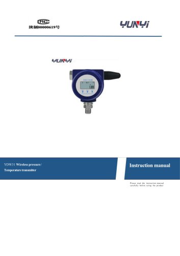
 YD31 series
4 Pages








- Kiln
- Flowmeter
- Temperature probe
- Volume flow monitor
- Liquid flow monitor
- Resistance temperature sensor
- Analog pressure transmitter
- Waterproof flow meter
- Gas flow monitor
- Level probe
- Digital temperature control
- Stainless steel flow monitor
- Liquid level sensor
- Pressure switch
- Industrial flow monitor
- Analog pressure gauge
- Waterproof pressure transmitter