- Catalogs
- Xi'an Aigtek Electronic Technology Co., Ltd.
- ATA-L20 User Manual
ATA-L20 User Manual
1 /20Pages

ATA-L20 User Manual
1 /20Pages
Catalog excerpts

User Manual
Open the catalog to page 1
To ensure safe and proper use of this electrical equipment, please read the safety instructions on the following pages. For first-time readers of this manual, it is recommended to start with the product introduction below. Overview, features, application scenarios, functionality, and operating principles. Read the precautions and installation methods before using this product. For long-term continuous operation, turn off the output for 5 minutes before disconnecting the power supply. Introduction to the front and rear panels of the device. Connection methods and precautions when using the device....
Open the catalog to page 2
To ensure safe use, please adhere to the following warnings and precautions. Aigtek assumes no responsibility for damages caused by failure to comply with these warnings and precautions. All warning messages in this user manual are intended to prevent serious accidents. Please comply strictly. 1. This device must be grounded during use to avoid the risk of electric shock. 2. When the three-pronged power plug of the device is connected to a three-pronged power socket with a protective earth connection, the device will automatically be grounded. Before connecting to the power supply, verify that...
Open the catalog to page 3
1. Product Introduction1.1 Product Overview • The ATA-L20 is a constant voltage output power amplifier with a bandwidth of 40Hz~150kHz, a maximum output voltage of 1200Vrms, a maximum continuous output power of 2600VA, and a maximum pulse output power of 6500VA. • This product features four-quadrant output characteristics, capable of both sourcing and sinking current, making it suitable for driving various types of loads. This product has a bandwidth of 40Hz~150kHz, a maximum output voltage of 1200Vrms, a maximum continuous output power of 2600VA, and a maximum pulse output power of 6500VA. The...
Open the catalog to page 5
This product comprises the control adjustment module, amplifier module, power supply module, auxiliary power module, monitoring module, and output control module. • The control adjustment module manages system control parameter adjustments. • The amplifier module performs voltage and power amplification. • The power supply and auxiliary power modules provide internal power to the device. • The output monitoring module enables monitoring of voltage and current outputs. Power Amplifier ATA-L20 User Manual
Open the catalog to page 6
To ensure safe use of this device, users should read the "Safety Instructions" section of this manual before operating the equipment. • If the outer surface of the packaging box shows any abnormalities (e.g., defects, dents), carefully inspect the device after removing it from the box to ensure no damage has occurred. • After opening the packaging, verify that all items are present. • If defects, dents of the carton, or missing accessories are found, contact Aigtek or its distributor immediately. • This product features sensitive overcurrent protection. If the instrument loses output and reverts...
Open the catalog to page 7
• Do not place the device with its rear or side facing downward. • Ensure that all four support feet are on a flat surface such as a desktop. • This device is intended for indoor use, at altitudes below 2000 meters. • The device uses a fan for forced air cooling. Ensure that the air intake and exhaust ports are at least 200 cm away from walls to allow proper ventilation. • Install the device in locations that meet the following temperature and humidity requirements: • Areas with flammable gases. • Outdoor locations, under direct sunlight, or near fire or heat sources. • Locations with corrosive...
Open the catalog to page 8
3. Panel Description 3.1 Front Panel ② Figure 2: Front Panel Diagram Power Amplifier ATA-L20 User Man
Open the catalog to page 9
® LCD Display: Shows amplifier parameter settings and operating status. ® Buttons (from left to right): Mode switch, frequency switch, impedance switch, output switch. a. Mode Switch: STEADY (continuous mode), PULSED (pulse mode). b. Frequency Switch: FREQ RG 0.04~20kHz, 10kHz~150kHz. c. Impedance Switch: ROUT 4.3ohm/8.6ohm/17ohm/35ohm/69ohm/138ohm/277ohm/554ohm, 1.7ohm/3.4ohm/6.9ohm/13.8ohm/28ohm/55ohm/111ohm/222ohm. d. Output Switch: POWER OFF, OUTPUT OFF, OUTPUT ON. Function varies depending on the interface, as described below. Power Button: Turns on the power rail and enters Interface 2...
Open the catalog to page 10
Output Button: Turns off the output and returns to Interface 2. In this interface, the mode switch and range switch buttons are disabled, and the frequency switch button functions as a save button; pressing it saves the current test parameters. ③ Adjustment Knob: Adjusts the output voltage percentage within the selected range. Clockwise rotation increases the gain, while counterclockwise rotation decreases the gain. Press the adjustment knob to toggle between coarse adjustment (1% step) and fine adjustment (0.1% step). ④ NC. ⑤ RS232: RS232 program control interface. ⑥ Input: BNC signal input...
Open the catalog to page 11
0^0 O o O o O O^O^O O O o o O. O^O^O O O o O O O^O^O O O o O, 0 0^0 OOO0OOOOOOOOO0OOOOOOOOOOOOOOO0OOO Figure 3: Rear Panel Diagram ® Power Switch: Circuit breaker switch.
Open the catalog to page 12
4. Device Connections and Settings4.1 Signal Generator The input impedance of this product is 10kQ. To accurately obtain the voltage, the signal generator output • Use coaxial cables for input connections. • The input terminal of this product should be connected to the output terminal of the signal generator; The output terminal should be connected to the load under test; The monitoring port can be connected to an oscilloscope. • When operating at high frequencies, the inductance of the cables may reduce the output voltage, limiting the maximum power delivered to the load. For capacitive loads,...
Open the catalog to page 13
5. Detailed Specifications Maximum Continuous Output Power 2600VA Note: ® During operation, the device must be used strictly within the specified bandwidth, maximum output voltage, and load limits. Over-range operation is strictly prohibited. ® The load impedance should be referenced according to the currently set output impedance (within the range of 90%R to -500%R without damage). Power Amplifier ATA-L20 User Manual
Open the catalog to page 14All Xi'an Aigtek Electronic Technology Co., Ltd. catalogs and technical brochures
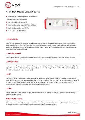 ATG-2161 Power Signal Source
2 Pages
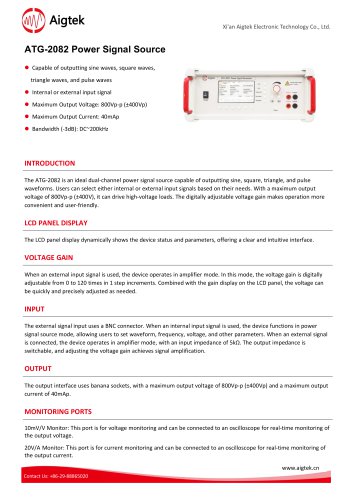 ATG-2082 Power Signal Source
2 Pages
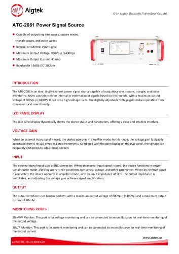 ATG-2081 Power Signal Source
2 Pages
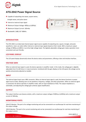 ATG-2042 Power Signal Source
2 Pages
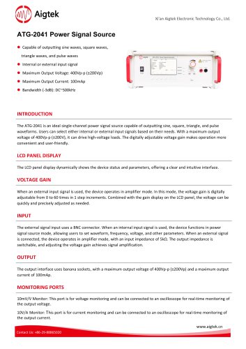 ATG-2041 Power Signal Source
2 Pages
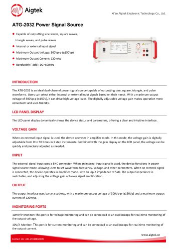 ATG-2032 Power Signal Source
2 Pages
 ATG-2031 Power Signal Source
2 Pages
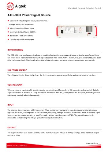 ATG-3090 Power Signal Source
2 Pages
 ATG-3080 Power Signal Source
2 Pages
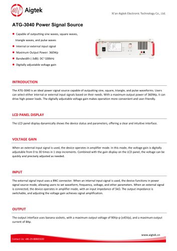 ATG-3040 Power Signal Source
2 Pages
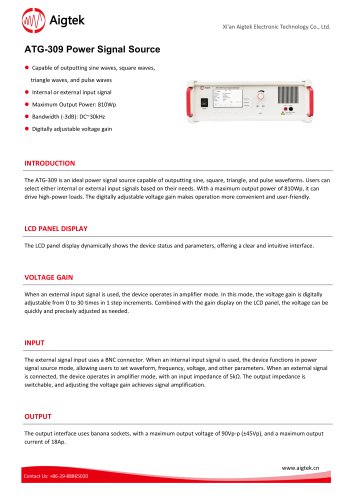 ATG-309 Power Signal Source
2 Pages
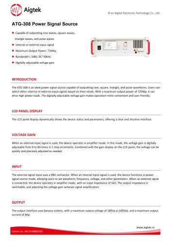 ATG-308 Power Signal Source
2 Pages
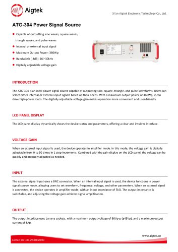 ATG-304 Power Signal Source
2 Pages
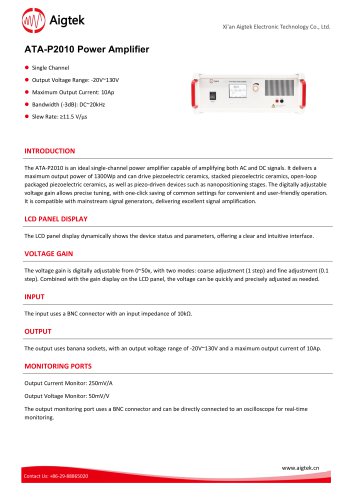 ATA-P2010 Power Amplifier
2 Pages
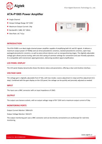 ATA-P1005 Power Amplifier
2 Pages
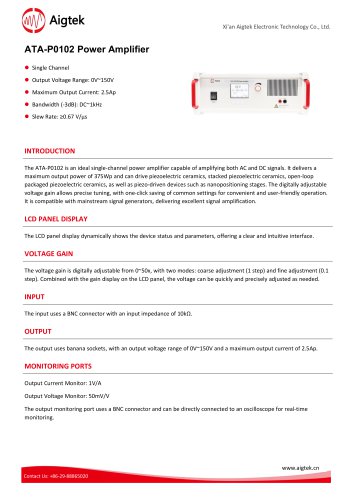 ATA-P0102 Power Amplifier
2 Pages
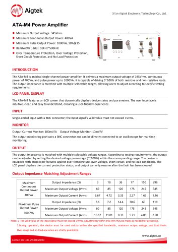 ATA-M4 Power Amplifier
2 Pages
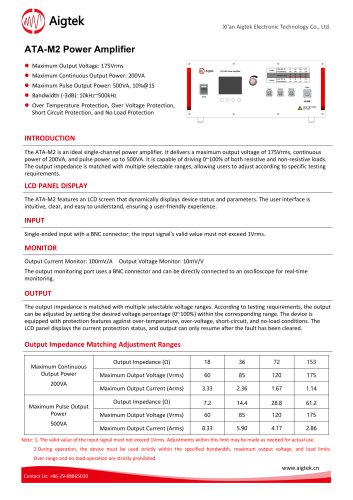 ATA-M2 Power Amplifier
2 Pages
 ATA-L8B Power Amplifier
2 Pages
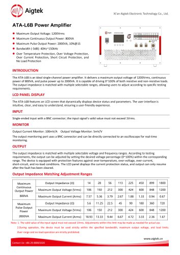 ATA-L6B Power Amplifier
2 Pages
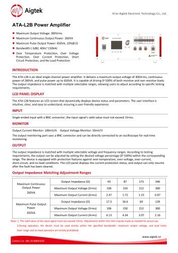 ATA-L2B Power Amplifier
2 Pages
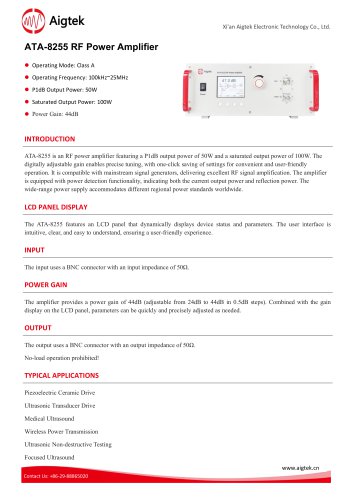 ATA-8255 RF Power Amplifier
2 Pages
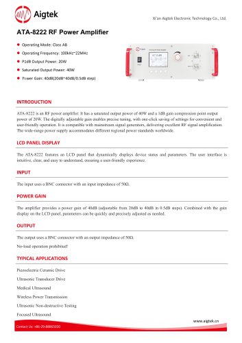 ATA-8222 RF Power Amplifier
2 Pages
 ATA-8202 RF Power Amplifier
2 Pages
 ATA-8152 RF Power Amplifier
2 Pages
 ATA-8126 RF Power Amplifier
2 Pages
 ATA-8055 RF Power Amplifier
2 Pages
 ATA-5620 Preamplifier
2 Pages
 ATA-5610 Preamplifier
2 Pages
 ATA-5520 Preamplifier
2 Pages
 ATA-5510 Preamplifier
2 Pages
 ATA-5420 Preamplifier
2 Pages
 ATA-5410 Preamplifier
2 Pages
 ATA-5310 Preamplifier
2 Pages
 ATA-5320 Preamplifier
2 Pages
 ATA-5220 Preamplifier
2 Pages
 ATA-5210 Preamplifier
2 Pages
 ATA-5120 Preamplifier
2 Pages
 ATA-318 Power Amplifier
2 Pages
 ATA-318 Power Amplifier
2 Pages
 ATA-315 Power Amplifier
2 Pages
 ATA-314 Power Amplifier
2 Pages
 ATA-8152 RF Power Amplifier
2 Pages
 ATA-8126 RF Power Amplifier
2 Pages
 ATA-8061 RF Power Amplifier
2 Pages
 ATA-8055 RF Power Amplifier
2 Pages
 ATA-8222 RF Power Amplifier
2 Pages
 ATA-8202 RF amplifier
2 Pages
 ATA-315 Power Amplifier
2 Pages
 ATA-314 Power Amplifier
2 Pages
 ATA-8202 RF Power Amplifier
2 Pages
 ATA-3090C Power Amplifier
2 Pages
 ATA-3080C Power Amplifier
2 Pages
 ATA-3040C Power Amplifier
2 Pages
 L8B Power Amplifier
2 Pages
 L2B Power Amplifier
2 Pages
 L20 Power Amplifier
2 Pages


- DC power supply
- AC/DC power supply
- Signal amplifying integrated circuit
- Tabletop power supply
- Variable-output power supply
- Rack-mount power supply
- Electronic equipment power supply
- High-voltage power supply
- Digital power supply
- Voltage amplifier
- Stabilized power supply
- DC amplifier
- Measuring amplifier
- Digital amplifier
- Electronic amplifier
- Pulse generator