- Catalogs
- Xi'an Aigtek Electronic Technology Co., Ltd.
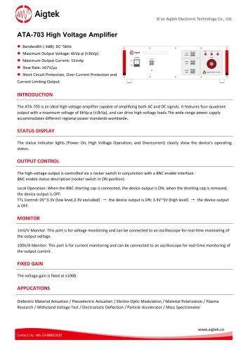
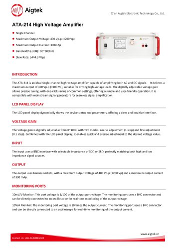
- ATA-214 High Voltage Amplifier
- Company
- Products
- Catalogs
- News & Trends
- Exhibitions
ATA-214 High Voltage Amplifier
1 /1Page
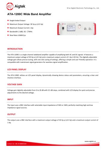
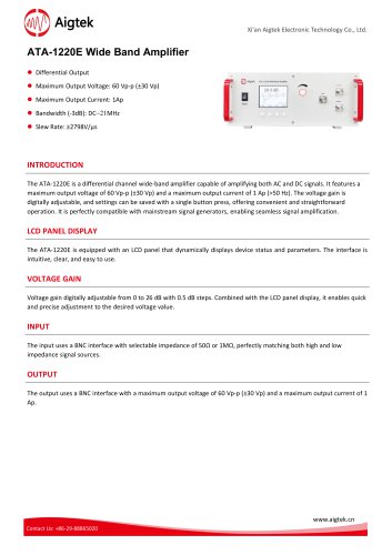
ATA-214 High Voltage Amplifier
1 /1Page
Catalog excerpts
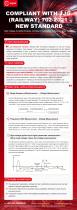
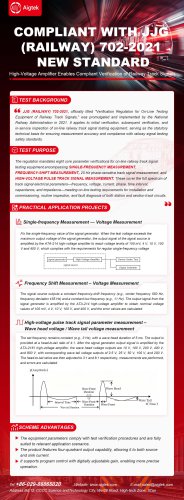
44 JJG (RAILWAY) 702-2021, officially titled "Verification Regulation for On-Line Testing Equipment of Railway Track Signals/' was promulgated and implemented by the National Railway Administration in 2021. It applies to initial verification, subsequent verification, and in-service inspection of on-line railway track signal testing equipment, serving as the statutory technical basis for ensuring measurement accuracy and compliance with railway signal testing safety standards. The regulation mandates eight core parameter verifications for on-line railway track signal testing equipment,encompassing SINGLE-FREQUENCY MEASUREMENT, FREQUENCY-SHIFT MEASUREMENT, 25 Hz phase-sensitive track signal measurement, and HIGH-VOLTAGE PULSE TRACK SIGNAL MEASUREMENT. These cover the full spectrum of track signal electrical parameters—frequency, voltage, current, phase, time interval, capacitance, and impedance—meeting on-line testing requirements for installation and commissioning, routine inspection, and fault diagnosis of both station and section track circuits. gg PRACTICAL APPLICATION PROJECTS Single-frequency Measurement — Voltage Measurement Frequency Shift Measurement - Voltage Measurement The signal source outputs a constant frequency-shift frequency (e.g., center frequency 550 Hz, frequency deviation ±55 Hz) and a constant low frequency (e.g., 11 Hz). The output signal from the signal generator is amplified by the ATA-214 high-voltage amplifier to obtain nominal voltage values of 100 mV, 4 V, 10 V, 100 V, and 400 V, and the error values are calculated. The set frequency remains constant (e.g., 3 Hz), with a wave head duration of 5 ms. The output is provided at a head-to-tail ratio of 4:1. After the signal generator output signal is amplified by the ATA-2161 high-voltage amplifier, the wave head voltage outputs are 10 V, 100 V, 200 V, 400 V, and 800 V, with corresponding wave tail voltage outputs of 2.5 V, 25 V, 50 V, 100 V, and 200 V. The head-to-tail ratios are then adjusted to 3:1 and 8:1 respectively, measurements are performed, and errors are calculated. j'ff] SCHEME ADVANTAGES ► The equipment parameters comply with test verification procedures and are fully suited to relevant application scenarios. Website: www.aigtek.com E-mail:[email protected] Address:Bd. 12, CCCC Science andTechnology City, Wei26 Road, High-tech Zone, Xi'an
Open the catalog to page 1All Xi'an Aigtek Electronic Technology Co., Ltd. catalogs and technical brochures
 ATG-2161 Power Signal Source
2 Pages
 ATG-2082 Power Signal Source
2 Pages
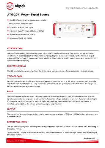 ATG-2081 Power Signal Source
2 Pages
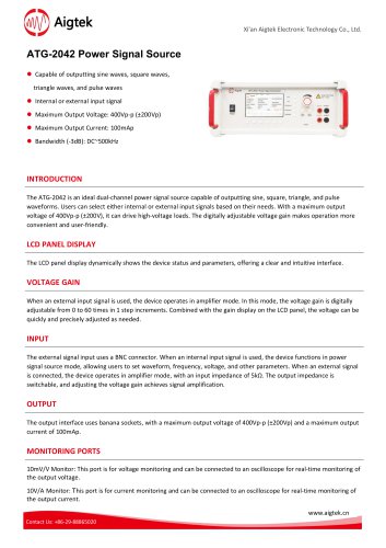 ATG-2042 Power Signal Source
2 Pages
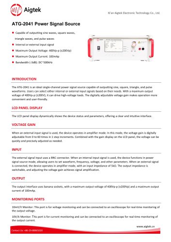 ATG-2041 Power Signal Source
2 Pages
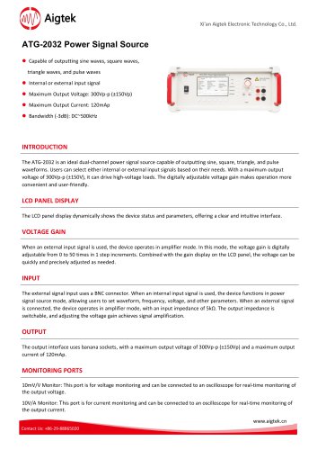 ATG-2032 Power Signal Source
2 Pages
 ATG-2031 Power Signal Source
2 Pages
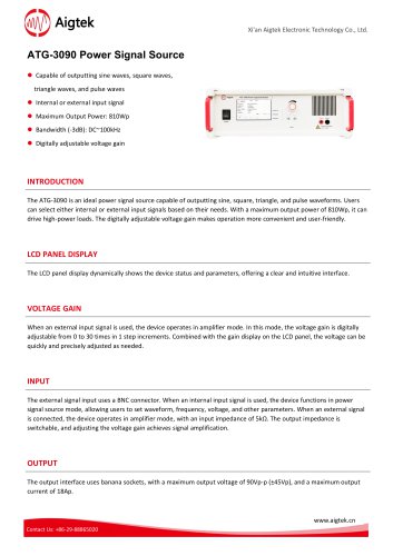 ATG-3090 Power Signal Source
2 Pages
 ATG-3080 Power Signal Source
2 Pages
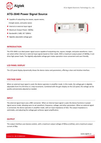 ATG-3040 Power Signal Source
2 Pages
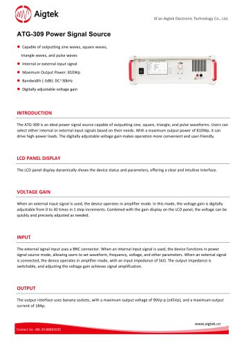 ATG-309 Power Signal Source
2 Pages
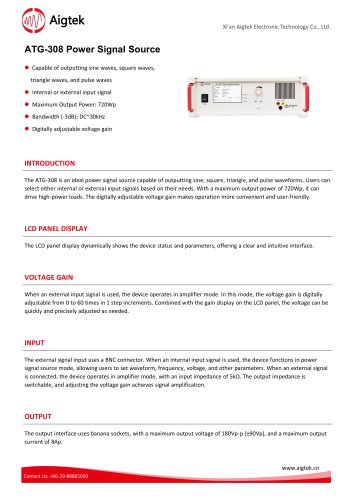 ATG-308 Power Signal Source
2 Pages
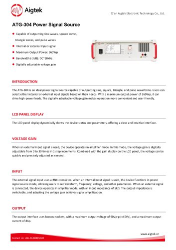 ATG-304 Power Signal Source
2 Pages
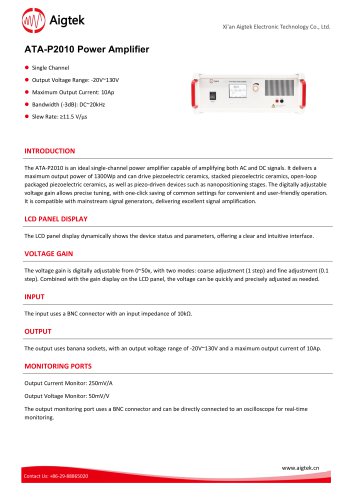 ATA-P2010 Power Amplifier
2 Pages
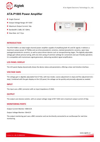 ATA-P1005 Power Amplifier
2 Pages
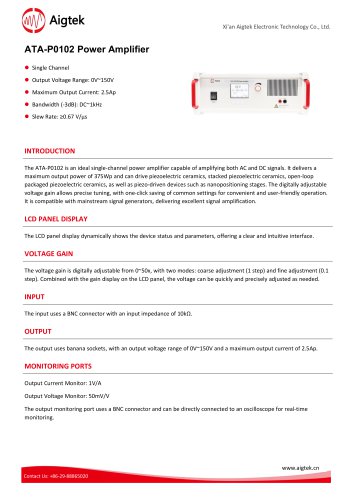 ATA-P0102 Power Amplifier
2 Pages
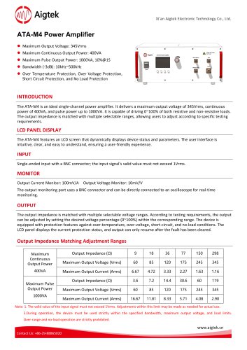 ATA-M4 Power Amplifier
2 Pages
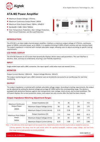 ATA-M2 Power Amplifier
2 Pages
 ATA-L8B Power Amplifier
2 Pages
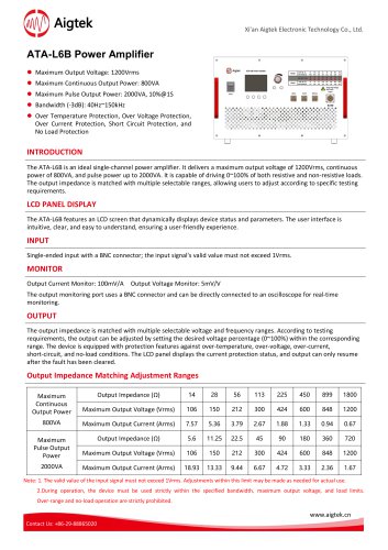 ATA-L6B Power Amplifier
2 Pages
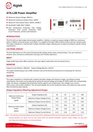 ATA-L2B Power Amplifier
2 Pages
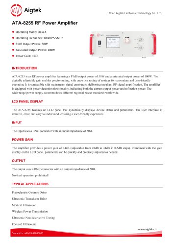 ATA-8255 RF Power Amplifier
2 Pages
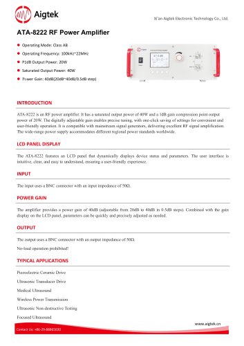 ATA-8222 RF Power Amplifier
2 Pages
 ATA-8202 RF Power Amplifier
2 Pages
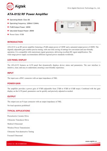 ATA-8152 RF Power Amplifier
2 Pages
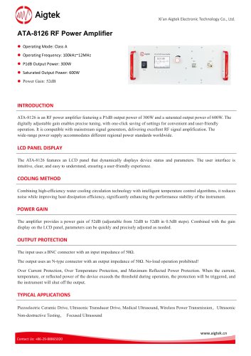 ATA-8126 RF Power Amplifier
2 Pages
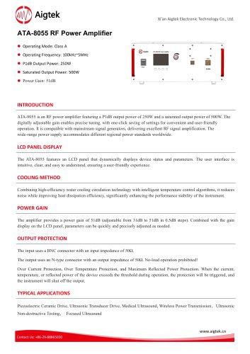 ATA-8055 RF Power Amplifier
2 Pages
 ATA-5620 Preamplifier
2 Pages
 ATA-5610 Preamplifier
2 Pages
 ATA-5520 Preamplifier
2 Pages
 ATA-5510 Preamplifier
2 Pages
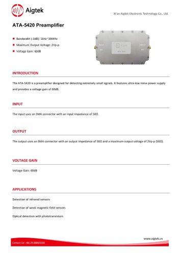 ATA-5420 Preamplifier
2 Pages
 ATA-5410 Preamplifier
2 Pages
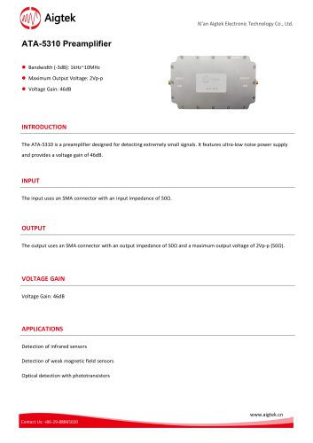 ATA-5310 Preamplifier
2 Pages
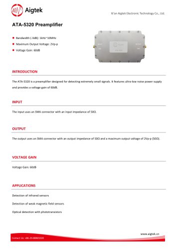 ATA-5320 Preamplifier
2 Pages
 ATA-5220 Preamplifier
2 Pages
 ATA-5210 Preamplifier
2 Pages
 ATA-5120 Preamplifier
2 Pages
 ATA-318 Power Amplifier
2 Pages
 ATA-318 Power Amplifier
2 Pages
 ATA-315 Power Amplifier
2 Pages
 ATA-314 Power Amplifier
2 Pages
 ATA-8152 RF Power Amplifier
2 Pages
 ATA-8126 RF Power Amplifier
2 Pages
 ATA-8061 RF Power Amplifier
2 Pages
 ATA-8055 RF Power Amplifier
2 Pages
 ATA-8222 RF Power Amplifier
2 Pages
 ATA-8202 RF amplifier
2 Pages
 ATA-315 Power Amplifier
2 Pages
 ATA-314 Power Amplifier
2 Pages
 ATA-8202 RF Power Amplifier
2 Pages
 ATA-3090C Power Amplifier
2 Pages
 ATA-3080C Power Amplifier
2 Pages
 ATA-3040C Power Amplifier
2 Pages
 L8B Power Amplifier
2 Pages
 L2B Power Amplifier
2 Pages
 L20 Power Amplifier
2 Pages


- Power supply unit
- DC power supply
- AC/DC power supply
- Signal amplifying integrated circuit
- Tabletop power supply
- Variable-output power supply
- Rack-mount power supply
- Power amplifying integrated circuit
- Electronic equipment power supply
- High-voltage power supply
- Measuring amplifier
- Digital power supply
- DC amplifier
- Stabilized power supply
- Electronic amplifier
- Pulse generator