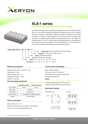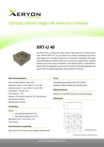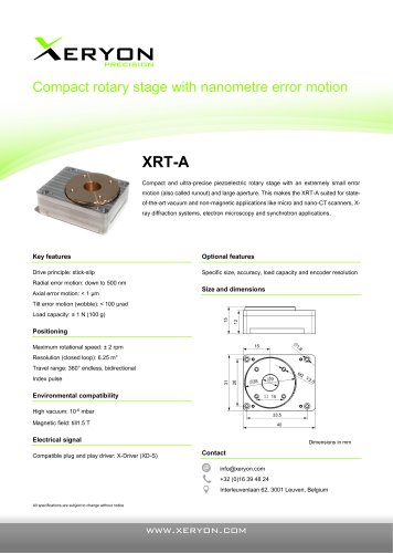
Catalog excerpts

Xeryon compact driver for ultrasonic stages (XD-C) Revision 1.5 dd. 09/09/2018 © Copyright by Xeryon BVBA, Interleuvenlaan 62, 3001 Leuven, Belgium All rights reserved. No part of this manual may be duplicated, reproduced, stored in an information system or processed or transferred in any other form without prior express written permission of Xeryon BVBA.
Open the catalog to page 1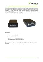
16. Introduction The XD-C provides a complete solution for controlling Xeryon’s ultrasonic stages. The controller reads the integrated encoder, generates and amplifies the driving signals and communicates with a host controller or PC through a simple ASCII protocol. The driver comes with a user-friendly Windows interface and LabVIEW driver to steer the stage in open and closed loop. Important steering parameters can be tuned digitally via the user interface. Specifications: Size: Mains power supply: Channels: Control: Serial communication: 80 x 54 x 23 mm 6-15 VDC 1 Open and closed loop COM...
Open the catalog to page 3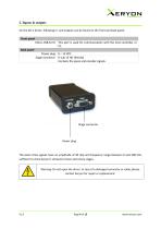
2. Inputs & outputs On the XD-C driver, following in- and outputs can be found on the front and back panel: The piezo drive signals have an amplitude of 30 Vpp and frequency range between 0 and 300 kHz, sufficient to drive Xeryon's ultrasonic linear and rotary stages. Warning: Do not open the driver. In case of a damaged connector or cable, please contact Xeryon for repair or replacement.
Open the catalog to page 4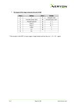
Pin layout of the stage connector (D-sub 15 HD) PIN # The encoder in the XRT-U rotary stage is single ended and has thus no I - / A - / B - signal.
Open the catalog to page 5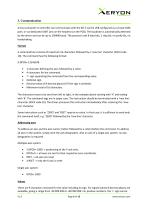
3. Communication A host computer or controller can communicate with the XD-C via the USB configured as a virtual COM port, or via dedicated UART pins on the headers (on the PCB). The baudrate is automatically detected by the driver and can be up to 230400 baud. The protocol uses 8 data bits, 1 stop bit, no parity bit, no handshaking. Format A command line consists of maximum 16 characters followed by a ‘new line’ character (ASCII code 10). The command has the following format: X:DPOS=-12345678 1 character defining the axis, followed by a colon. 4 characters for the command. ‘=’...
Open the catalog to page 6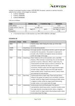
omitted, increasing the positive range to 999 999 999. No spaces, commas or periods should be added to the numbers. Only integers are allowed. • X:DPOS=-99999999
Open the catalog to page 7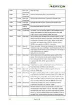
AERYDN PRECISION
Open the catalog to page 8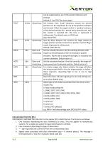
Information is sent back from the XD-C to the master (PC) in ASCII format. The format is as follows: 1. One character identifying the axis, followed by a colon. This only applies to multiple-axis systems. For a single-axis system the axis identification is omitted. 2. Four characters describing the type of information 3. '=' sign separating the command from the corresponding value 4. Signed value associated with that information (sign + 8 decimal places). The message is terminated with a 'new line' character (ASCII code 10).
Open the catalog to page 9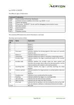
The different types of information:
Open the catalog to page 10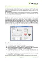
4. User interface To provide the user with a quick way to interact with the driver and the connected stage, a user interface is delivered with the XD-C. The use is simple and self-explanatory. It can be used for manual input and to run simple programs. More information regarding this user interface is given in the user manual of the stage. This user interface is not intended for interaction with other programs written in C, Labview, Matlab, etc. These programs should directly interact with the driver via the protocol described above. On request, C++ code is provided to ease interfacing....
Open the catalog to page 11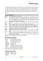
The settings file and program files are composed of the same commands that are used to directly talk to the XD-C. An important difference is that the User Interface uses position data in degrees, millimetre etc., while encoder units have to be used when talking directly to the XD-C. The conversion is automatically made by the User Interface. Similar conversions are made for speed (deg/s or mm/s). A few additional commands exist that affect the program flow and connection. These are not axis specific. Remark: Comment text should be preceded by a percentage sign. Example settings file...
Open the catalog to page 12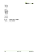
% Repeat 3 times the code above % Finish in the centre % Finish in the centre
Open the catalog to page 13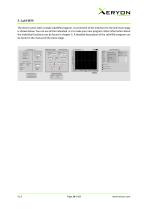
5. LabVIEW The driver comes with a simple LabVIEW program. A screenshot of the interface for the XLS linear stage is shown below. You can use all the individual .vi’s to make your own program. More information about the individual functions can be found in chapter 5. A detailed description of the LabVIEW program can be found in the manual of the piezo stage.
Open the catalog to page 14
6. Customer service • Contact: support@xeryon.com • Address: Interleuvenlaan 62, B-3001 Leuven, Belgium • Phone: +32 (0)16 39 48 24 • Website: www.xeryon.com
Open the catalog to page 15


