Catalog excerpts

wyler ag Inclination measuring systems Neigungsmesssysteme Im Holderli 13, CH - 8405 WINTERTHUR (Switzerland) E-Mail: wyler@wylerag.com Web: www.wylerag.com
Open the catalog to page 1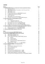
1. The ZEROTRONIC Sensor, the design and the digital measuring principle 7 1.2. ZEROTRONIC-sensors / Two sensor- types Type 3 and Type C 7 1.8 ZERO POINT and long-term stability 10 2. SHORT DESCRIPTION OF THE MEASUREMENT ANALYSIS 13 2.2 Measurement-analysis with a LEVELMETER 2000 15 2.3 Measurement-analysis with a BlueMETER sigma 15 3. Changing addresses of the sensors and measuring instruments connected 17 3.1 Principal description of the LEVELMETER 2000 17 3.2 Principal description of the BlueMETER sigma 19 4. INTERFACES ZEROTRONIC-SENSORS TO...
Open the catalog to page 2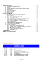
D3 Possible Configurations (Example with ZEROTRONIC-Sensors) 36 E1 BlueTC with and without wireless module (Details) 37 E1.2 Typical configurations with BlueTC 38 E2.1 Combine a group of instruments to a measurement group 39 using the function „JOIN“ In radio transmission mode E2.2 Unhinge an instrument in the radio mode from a group, 40 using the function „LEAVE“ E3 Renewed connection of a measuring group 40 E4 Typical configurations with BlueTC 41 E5.1 Functional menu with BlueTC / Structure 42 E5.2 Operating the BlueTC / Short description of the...
Open the catalog to page 3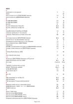
Applications with ZEROTRONIC Sensors A BlueTC E BlueTC / Dimensions of BlueTC E5.5 BlueTC / Operating the BlueTC E5.2 calibration of digital systems 1.6 Changing addresses of the sensors 3 Command / Response data frame structure B4 description of the measurement analysis 2 Difference in characteristics of the 2 Sensors 1.2 Digital Sensor-Family ZEROTRONIC 1.1 DYNAM / The measuring-software for ZEROTRONIC-sensors 2.4 Dynamic Characteristics of ZEROTRONIC-sensors 1.5 Express Repair Service, ERS F High temperature range 1.6 Interfaces...
Open the catalog to page 4
Startup of the BlueTC Storage / SENSOR Storage T Transceiver T/C Two sensor- types - Type 3 and Type C Typical configurations with BlueTC U / V Vibrations / Shock W WyBus Module WyBus-Development-Kit Z ZERO POINT and long-term stability ZEROTRONIC Sensor, the design and the digital measuring principle ZEROTRONIC-sensors Type 3 ZEROTRONIC-sensors Type C
Open the catalog to page 5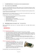
The ZEROTRONIC Sensor, the design and the digital measuring principle The sensors of the ZEROTRONIC family have a digital inclination sensor and a digital data transmission. Working digitally, they provide the option to compensate for temperature changes and allow data communication over long distances without any loss of data. The combination of all these features ensures that these sensors fulfil highest requirements regarding precision, resolution, sensitivity and temperature stability. ZEROTRONIC-sensors have established themselves in the market as the benchmark when it comes to...
Open the catalog to page 6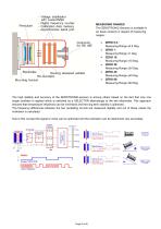
- Voltage stabilisator with Level-Shifter - Digital frequency counter Pendulum _ Calibration data memory - Asynchronous serial port Mounting bracket MEASURING RANGES The ZEROTRONIC-Sensors is available in six basic versions in respect of measuring ranges: • ZERO 0.5; Measuring Range ±0.5 Deg. • ZERO 1; Measuring Range ±1 Deg. • ZERO 10; Measuring Range ±10 Deg. • ZERO 30; Measuring Range ±30 Deg. • ZERO 45; Measuring Range ±45 Deg. • ZERO 60; Measuring Range ±60 Deg. The high stability and accuracy of the ZEROTRONIC-sensors is among others based on the fact that only one single oscillator...
Open the catalog to page 7
The following list of characteristics should allow a proper differentiation and proper application of the 2 sensors: 1.3 ZEROTRONIC Type 3 • High resolution, high precision for inclinations up to 10° • Excellent signal to noise ratio Some typical applications for the ZEROTRONIC Type 3 Applications, where high precision and high resolution is first priority and where only small inclinations are measured: • Adjustment of machines (e.g. pitch and roll) • Precise adjustment of absolute zero • Precise measurement of small inclinations in heavy duty environment; e.g. exposure to...
Open the catalog to page 8
CALIBRATION OF DIGITAL SYSTEMS Each single sensor is individually calibrated over the complete measuring range as well as over the complete temperature range the sensor is going to be used. These calibration values are stored as reference points in the EPROM of the sensor. Two temperature calibrations are available: The standard temperature calibration is well suited for sensors which are used in a typical laboratory or a machine shop environment: Temperatures around 20° C and slow temperature changes. The HTR (High temperature range) calibration is suited for those sensors which are...
Open the catalog to page 9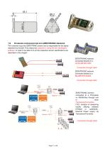
1.9 Standard.configurations with ZEROTRONIC-Sensors The customer buys the ZEROTRINIC-sensor and is responsible for the signal treatment by himself. This means the customer is using the own developed software. In order to be able to do so the respective sensor specifications are described in this chapter. ZEROTRONIC-sensors connected directly to a LEVELMETER 2000 Connection through cable ZEROTRONIC-sensors connected directly to a BlueMETER SIGMA Connection through cable ZEROTRONIC-sensors connected to a PC/Laptop on RS485-Bus through one or more Transceiver/Converters (T/C). Analyze of...
Open the catalog to page 10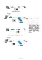
Connection through cable ZEROTRONIC-sensors connected to a PC/Laptop through two or more BlueTC. The BlueTC is used as interface for data transmission through cable or wireless connection. To each BlueTC up to 8 sensors may be connected. In total the system can handle 64 addresses. Because every TC also uses one address a total of 56 sensors can be connected (64 minus 8 BlueTC addresses). Analyze of measuring results utilizing software LabEXCEL. Connection through wireless data transmission
Open the catalog to page 11
Short description of the measurement analysis Important: Before starting any precision measurement the ZEROTRONIC sensor should be powered for at least 15 minutes. This is to avoid a possible start-up drift of the electronic components (warm up period). 2.1 WyBus Module 2.1.1 WyBus-Development-Kit For users who would like to define and program their own measuring software for WYLER inclination sensors, WYLER AG provides a WyBus-development-kit with self-explaining samples. An essential part of these examples is a WyBus core (a *.dll-file) allowing a standardised and...
Open the catalog to page 12All WYLER AG catalogs and technical brochures
-
wylerConnect Connection option
12 Pages
-
LED CROSS / LED-KREU
3 Pages
-
wylerCONNECT The interface
4 Pages
-
Clinotronic S
8 Pages
-
Monitoring Wind Turbines
2 Pages
-
WYLER CATALOGUE 2018
216 Pages
-
WYLER miniCATALOGUE 2017
16 Pages
-
CABLES + ACCESSOIRES
4 Pages
-
CROSS
3 Pages
-
LEVELMETER 2000
3 Pages
-
BlueMETER BASIC
3 Pages
-
Monitoring
6 Pages
-
BlueSYSTEM SIGMA
14 Pages
-
wylerDYNAM
4 Pages
-
LEVELMATIC
4 Pages
-
BlueSYSTEM BASIC
8 Pages
-
MINILEVEL NT
6 Pages
-
nivelSWISS-D
3 Pages
-
nivelSWISS
3 Pages
-
BlueCLINO High Precision
8 Pages
-
CLINO 2000
4 Pages
-
Clinotronic PLUS
5 Pages
-
BluemETER SIgma
7 Pages
-
WYLER AG
104 Pages
-
WYLER PRODUCTS
215 Pages
-
WW76
1 Pages
-
WW59
1 Pages
-
WW53
1 Pages
-
WW56
1 Pages
-
WW55
1 Pages
-
BlueCLINO
4 Pages
-
CLINO_PLUS
4 Pages
-
clino2000
2 Pages
-
katalog_2012/BlueSYSTEM
11 Pages
-
Wasserwaagen_Clinometer_alle
26 Pages
-
katalog_2012/Sensoren
22 Pages
-
WYLER CATALOGUE 2009
166 Pages
Archived catalogs
-
Wyler Catalogue 2006
164 Pages


