
- Catalogs
- Wuxi Danikor Automation Technology Co.,Ltd
- Danikor Frame Arms


- Company
- Products
- Catalogs
- News & Trends
- Exhibitions
Danikor Frame Arms
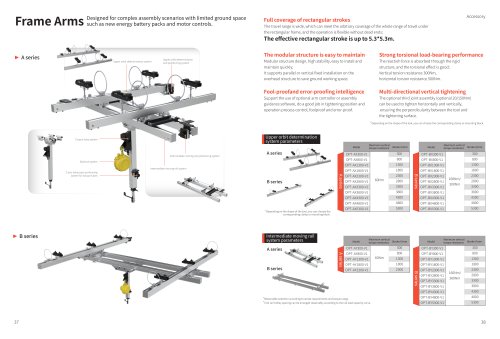
Danikor Frame Arms
Overview
The document describes Frame Arms designed for complex assembly scenarios with limited ground space, such as new energy battery packs and motor controls. The system is modular and supports flexible installation and operation.
Main Sections and Summaries
1. Frame Arms Series
Two main series are presented: A series and B series. Both series include components such as the upper orbit determination system, intermediate moving rail system, torque tube system, balance system, and Z-axis telescopic positioning system for torque tubes.
2. Upper Orbit Determination System
This system provides positioning and torque resistance capabilities. Models are specified for both A and B series, with parameters including maximum vertical torque resistance and stroke length (X/mm). The system allows selection of clamps or mounting blocks depending on tool shape.
3. Intermediate Moving Rail System
Parameters for this system include stroke requirements and torque range. The tool rail trolley spacing can be arranged based on the rail load capacity curve. Models for both A and B series are listed with maximum vertical torque resistance and stroke length (X/mm).
4. Accessories
Accessories are available for the B series, with specifications for maximum vertical torque resistance and stroke length (Y/mm).
5. Key Features and Benefits
- Modular Structure: High stability, easy installation and maintenance, supports parallel or vertical fixed installation on overhead structures to save ground space.
- Fool-proof and Error-proof Intelligence: Optional arm controller or assembly guidance software ensures precise tightening position and operation control.
- Full Coverage of Rectangular Strokes: Wide travel range allowing flexible operation without dead ends; effective rectangular stroke up to approximately 1.5 x 1.5 meters.
- Strong Torsional Load-bearing Performance: Rigid structure absorbs reaction forces effectively; vertical torsion resistance up to 1000 Nm, horizontal torsion resistance up to 500 Nm.
- Multi-directional Vertical Tightening: Optional third joint assembly (with torque ratings of 50/100 Nm) enables tightening both horizontally and vertically, ensuring perpendicularity between tool and tightening surface.
6. Installation and Operation Recommendations
Depending on the tool shape, appropriate clamps or mounting blocks should be selected. The modular design facilitates quick maintenance and installation. The system supports flexible configurations to optimize space and operational efficiency.
Critical Parameters and Limitations
- Torque resistance varies by model and series; specific values are provided for vertical and horizontal resistance.
- Stroke lengths differ across models and must be selected based on assembly requirements.
- Tool rail trolley spacing must be arranged according to rail load capacity to ensure safety and performance.
Catalog excerpts
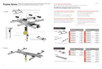
Efd IY1A A VVY% C Designed for complex assembly scenarios with limited ground space I" Id HIE AlMis such as new energy battery packs and motor controls. Full coverage of rectangular strokes The travel range is wide, which can meet the arbitrary coverage of the whole range of travel under the rectangular frame, and the operation is flexible without dead ends; Upper orbit determination system Upper orbit determination and positioning system Intermediate moving rail positioning system Intermediate moving rail system The effective rectangular stroke is up to 5. The modular structure is easy to maintain Modular structure design, high stability, easy to install and maintain quickly; It supports parallel or vertical fixed installation on the overhead structure to save ground working space. Support the use of optional arm controller or assembly guidance software, do a good job in tightening position and operation process control, foolproof and error-proof. ► 5.3m.Strong torsional load-bearing performance The reactioh force is absorbed through the rigid structure, and the torsional effect is good; Vertical torsion resistance 300Nm, horizontal torsion resistance 500Nm. The optional third joint assembly (optional 20/150Nm) can be used to tighten horizontally and vertically, ensuring the perpendicularity between the tool and the tightening surface. lending on the shape of the tool, you can choose the corresponding clamp or mounting block. Upper orbit determination system parameters_ Z-axis telescopic positioning system for torque tubes Intermediate moving rail system parameters A series B series Maximum vertical , , Model torque resistance stroke Y/mm Reasonable selection according to stroke requirements and torque range. *Tool rail trolley spacing can be arranged reasonably according to the rail load capacity curve. Maximum vertical Model torque resistance
Open the catalog to page 1All Wuxi Danikor Automation Technology Co.,Ltd catalogs and technical brochures
 Danikor Prodcuts Catalog
2 Pages
 Danikor Company Profile
46 Pages
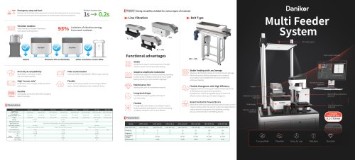 Flexible Feeding System
2 Pages
 Industrial Torque Screwdriver
29 Pages


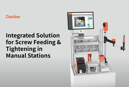
Archived catalogs
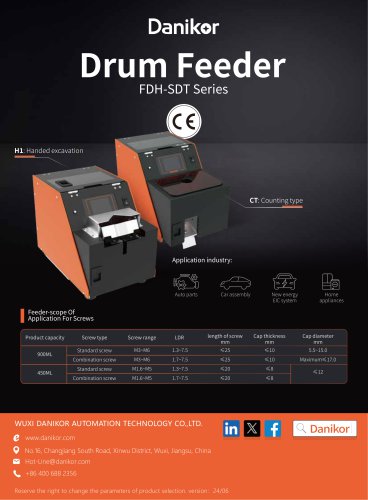 Screw Dispenser/Screw Presenter
2 Pages
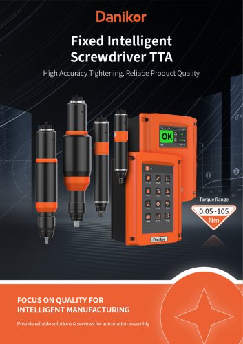 TTA PTT-ASF Series
5 Pages
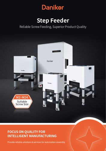 Step Feeder
4 Pages
 Flexible Feed System
7 Pages
 Vibration Bowl Feeder
3 Pages
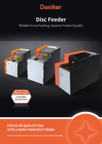 Disc Feeder
5 Pages
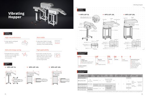 Danikor Vibrating Hopper
1 Page
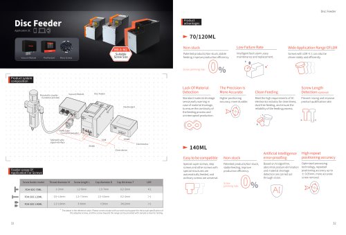 Danikor Disc Feeder
1 Page
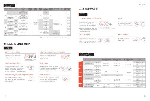 Danikor Step Feeder
1 Page
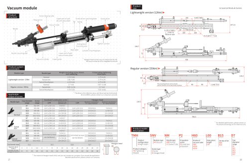 Danikor Vacuum module
1 Page
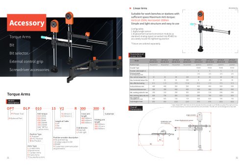 Danikor Torque Arms
1 Page
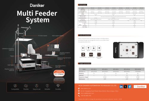 Flexible Feeding System
2 Pages
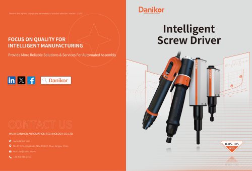 Smart Electric Screwdriver
14 Pages


- Danikor feeder
- Measurement software
- Danikor electric screwdriver
- Screwdriver
- Danikor brushless electric screwdriver
- Danikor corded electric screwdriver
- Danikor straight electric screwdriver
- Danikor automatic feeder
- Danikor DC electric screwdriver
- Vibratory feeder
- Danikor bulk material feeder
- Cordless electric screwdriver
- Pistol electric screwdriver
- Danikor electric screwdriver with torque control
- Calibration software
- Danikor semi-automatic electric screwdriver
- Danikor automatic electric screwdriver
- Danikor screwing unit
- Battery-powered electric screwdriver
- Continuous-motion feeder