
- Catalogs
- Wolong Electric Group
- WE3 series catalog


WE3 series catalog

WE3 series catalog
Wolong Electric Group Co., Ltd, founded in 1984 and listed on the Shanghai Stock Exchange in 2002, is a global leader with 55 subsidiaries and over 18,500 employees. The company specializes in three main product chains: Motor and Drives, Transformers, and Power Supply. The ATB Group, a subsidiary, has a history of over 90 years and includes several renowned brands. Wolong provides a wide range of products for both household and industrial applications.
The WE3 series of premium-efficiency three-phase asynchronous motors are available in frame sizes 80-355, with various enclosure, mounting, and terminal box options. They support multiple voltages and frequencies, with cooling options and thermal protection features, designed for ambient temperatures between -15°C to +40°C.
Wolong's quality assurance process is ISO 9001 certified, ensuring high standards from quotation to delivery. The motors comply with international standards, including IEC and DIN/EN, and bear the CE label under the Low Voltage Directive 2014/35/EC.
Detailed technical explanations are provided on three-phase alternating current, rated power, torque, speed, and connection types (star and delta). It also covers protection against electric shock, dust, and water ingress, with IP ratings from IP54 to IP65.
Various mounting arrangements are available, including foot-mounting and flange-mounting options. The motors can be installed in different positions, and the terminal boxes are rotatable for flexible connection.
The shaft ends are cylindrical and conform to IEC 50347 standards. Motors are equipped with internal threads for fitting pulleys and couplings, and the key and keyway are designed according to DIN 6885-1.
The motors are dynamically balanced, with vibration severity grades available for special requirements. Vibration velocity limits are specified according to IEC 60034-14 standards.
The document outlines key balancing according to DIN ISO 21940-32:2012, specifying types of key and keyway balancing. It emphasizes high-quality bearings and adherence to fit tolerances for reliable operation and vibration severity grade A as per IEC 60034-14.
Transmission elements must be dynamically balanced, with hub length matching key length to avoid unbalances. Torsionally flexible couplings require precise alignment to prevent vibrations and bearing damage.
Motors are equipped with fans for cooling, classified under IEC 60034-6 codes. Proper cooling requires maintaining space between the fan cowl and walls.
Motors use rolling-contact bearings, with frame size 180 and below being permanently lubricated, while size 200 and above are regreasable. A table specifies bearing types for different frame sizes and poles.
The document provides permissible radial forces for different frame sizes and poles, ensuring a calculated life of 20,000 hours. Rated power values are for S1 service type at 50 Hz and 40°C, with adjustments for higher temperatures or altitudes.
Efficiency classes (IE1 to IE4) are detailed for different poles and frequencies. Tolerances for electrical values are specified according to DIN EN 60034-1.
Various service types (S1 to S10) are defined, with specific requirements for each. Motors are designed for temperature class 155 (F), with insulation protecting against environmental factors.
Thermal motor protection is crucial, with options for thermistor detectors and PTC thermistors. Space heaters are available to reduce condensation, with specifications for supply voltage and heating output.
The permissible number of starts per hour is outlined for different shaft heights and poles, ensuring regular intervals and load conditions.
This document provides detailed technical specifications and installation guidelines for the WE3 Series three-phase asynchronous motors, including electrical design, product information requirements, type designation, technical parameters, and installation dimensions.
A maximum of six PTC thermistors can be connected to one control unit.
According to Regulation 640/2009, the nameplate must include 20 points of technical data, such as type, rated voltage, current, power, efficiency, service factor, duty type, frequency, power factor, speed, weight, connection, protection class, insulation class, noise, manufacturing number, bearing types, production date, and QR code.
The type designation for three-phase squirrel-cage a.c. motors includes the manufacturer's name, environmental condition code, poles, frame size, and series information.
Detailed tables of technical parameters for 2, 4, and 6 pole motors at 50Hz are provided, including rated output, current at various voltages, speed, efficiency, power factor, starting torque, starting current, breakdown torque, weight, noise, moment of inertia, and torque at different loads.
Installation dimensions for B3 and B5 cast iron motor frames are detailed, including frame sizes and dimensions for various components like shaft diameter, length, and mounting holes.
The tables provide comprehensive data on motor performance across different models and configurations, highlighting efficiency, power factor, and torque characteristics critical for selecting the appropriate motor for specific applications.
Catalog excerpts

WE3 Series of Premium - Efficiency Three - phase Asynchronous Motor WOLONG Pcnoer y,eur future
Open the catalog to page 1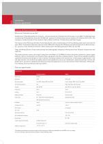
Introduction Cast iron specification Sincerity, Harmony and Creativity Who are we? And what can we offer? Established in 1984, Wolong Electric Group Co., Ltd was listed on the Shanghai Stock Exchange in June 2002. The Wolong Group currently has 55 Subsidiaries, more than 18.500 staff, assets of 3.2 billion and an annual revenue of 4.5 billion USD in 2016. The company is mainly focused on three product chains: Motor and Drives, Transformers and Power Supply. The history of the ATB Group (Antriebs Technik Bauknecht), with a shareholding of 100 % by Wolong, dates back more than 90 years. With 12...
Open the catalog to page 2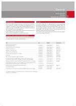
Quality assurance The entire order realisation process for electrical machines, from quotation to delivery including the integration of our suppliers, is based on a generally accepted quality assurance system pursuant to ISO 9001, which is constantly monitored and undergoes further development. The designs, technical data and illustrations contained in this documentation are subject to change. They are only binding upon written confirmation. 11 IEC 60072 only provides for dimensions but does not define any output classifications. (tolerances acc. to EN 50347)
Open the catalog to page 3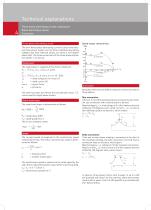
Technical explanations Three-phase alternating current, rated power Rated-load torque, speed Connection Three-phase alternating current The term three-phase alternating current is used if the existing three-phase system carries three individual alternating voltages that have identical values, but show a 120-degree phase shift. The three connections of the three-phase system are called L1, L2 and L3. Rated power The rated power is supplied at the motor's shaft end: PN = f3 x UN x IN x cos w x h [W] or PN = J~3 x UN x IN x cos w x h x 10-3 [kW] UN = rated voltage at the motor [V] The same formulae,...
Open the catalog to page 4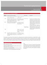
For all types of construction with the shaft end in a downward position, the design "with drip roof” is recommended, in order to prevent the ingress of water at the second non-drive shaft end. For all types of construction with the shaft end in an upward position, a suitable cover, which prevents the dropping of small parts onto the fan cowl, is a prerequisite. This does not apply when the motor is attached to a driven machine, which then provides cover. However, the cooling air flow may not be affected by such a cover. Motors that are installed out of doors must be protected against intensive...
Open the catalog to page 5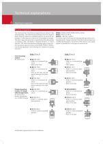
Technical explanations Mounting arrangements Mounting arrangements The most common mounting arrangements are shown in the following table. The dimensional drawings show the range of frame sizes for which the individual types of construction are available. Further types of construction are available on request. The basic type of construction is specified on the rating plate according to code I, IEC 60034-7. Standard motors, i.e. frame sizes 80 – 355, which are ordered as the basic types of construction (universal types of construction) IM B3, IM B5 or IM B14, can also be operated in the following...
Open the catalog to page 6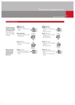
Technical explanations Types of construction Mounting arrangements Motors without end shield and rolling-contact bearing at the drive end Code I (Code II) IM B14 (IM 3601) –– Shaft in a horizontal position Code I (Code II) IM B34 (IM 2101) –– Shaft in a horizontal position –– Feet on the floor IM V18 (IM 3611) –– Shaft in a vertical downward position IM V17 (IM 2111) –– Shaft in a vertical downward position –– Feet on the wall IM V3 (IM 3031) –– Shaft in a vertical upward position Flange-mounting motors, FT flange with tapped holes up to frame size 160; former designation acc. to DIN: C-flange...
Open the catalog to page 7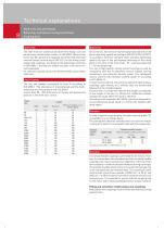
Technical explanations Shaft ends, Key and Keyway Balancing, mechanical running smoothness Coupling drive Shaft ends The shaft ends are cylindrical and both their design, size and performance classification conform to IEC 50347. Motors from frame size 80 upwards are equipped with shaft ends that have internal threads conforming to DIN 332-2 for the fitting of belt pulleys and couplings. The design of the featherkeys conforms to DIN 6885-1; the keys are always included in the motor delivery packages. On customer request, motors are delivered with a second free shaft end. The key and keyway correspond...
Open the catalog to page 8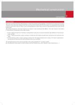
Mechanical construction Cooling method Cooling method The motors are fitted with fans made of plastic or metal that provide cooling regardless of the direction of rotation of the motor. The built-in fan moves the cooling air from the non-drive end to the drive end. For this reason, it is essential that the openings of the fan cowl ensure free air inflow. Correct cooling depends on observing a minimum space between the fan cowl and any existing wall. The cooling methods for electrical machines are stated in code according to IEC 60034-6. The code consists of the letters IC (International Cooling)...
Open the catalog to page 9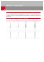
The motors are equipped with rolling-contact bearings on the drive end and the non-drive end. The bearings in motors up to and including frame size 180 are permanently lubricated. Motors of frame size 200 have a regreasable bearing. Other on request. These motors are fitted with an additional plate stating details about the specific lubricant, the quantity required and the greasing intervals. Bearing type (bearing selection can be changed according to customer needs) Frame size
Open the catalog to page 10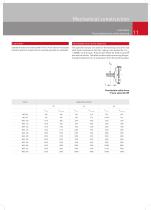
Standard motors are lubricated for life. In the case of increased load and extreme temperatures, special greases are available. Permissible forces at the shaft end The specified values are valid for the bearings and drive end shaft ends contained in this list, taking a calculated life of L10h = 20000 h as the basis. They are permitted for both horizontal and vertical shafts. The table contains data concerning the permissible radial force FR at a distance x from the shaft shoulder. Permissible radial force Frame sizes 80-355 Frame
Open the catalog to page 11All Wolong Electric Group catalogs and technical brochures
 Wolong ECM Vector Motor
16 Pages
 H-Optim
2 Pages
 ATB CD
144 Pages
 W Cast Iron motors
30 Pages
 EnergySaver
2 Pages



- Electromotor
- Synchronous motor
- Alternating current motor
- Multipole motor
- Electromotor for industrial applications
- Three-phase motor
- Servo-motor
- 4-pole motor
- Compact electromotor
- 2-pole motor
- IP55 motor
- High-efficiency electromotor
- Pump motor
- Permanent magnet motor
- Induction motor
- AC servo-motor
- 400 V motor
- 6-pole motor
- 8-pole motor