

Locking Assemblies and Bushes

Locking Assemblies and Bushes
- Clamping Bushes: Made primarily from GG25 cast iron, available in various sizes with specific dimensions. Part numbers are provided for easy identification.
- Taper Bushes: Interchangeable with Taper Lock bushes, specifications include bore diameter and screw starting torque. Part numbers indicate bore diameter.
- Locking Assemblies: Available in self-centering and non-self-centering variants, with calculations for minimum hub diameter included.
- Shrink Discs: Suitable for high torque applications, allowing quick dismantling without axial movement.
- Mounting Instructions: Detailed steps for installing clamping and taper bushes to ensure proper fit and function.
- Calculation Guidelines: Instructions for calculating minimum hub diameter using a formula for thick hollow cylinders, considering material type and application pressure.
- Components adhere to DIN 6885 standards, with specific tolerances and surface finish requirements.
- Maximum allowable surface finish is Rt max 16µm (Ra 3 µm - Rz 13 µm).
- Shaft and hub tolerances vary based on diameter.
- Consult engineering experts for application-specific advice and custom solutions.
- Ensure no axial movement during screw tightening and consider material properties when selecting components.
- Dimensions, weights, torque specifications, and screw details for clamping and taper bushes are provided.
- Tables include detailed specifications for locking assembly models, including dimensions, torque, thrust, and contact pressures.
- Coefficient K tables assist in calculating minimum hub diameter based on material type and application pressure.
- The series is being phased out and should not be used for new designs.
- Recommended hub outer diameter is specified for steel 1.1191 with a yield point of 310 N/mm² and factor C = 1.
Catalog excerpts

Locking Assemblies stock programme - selbstzentrierend & nicht selbstzentrierend Taper Bushes Taper Bushes - Selection Tables Bolt on Hubs for Taper Bushes Weld on Hubs for Taper Bushes Clamping Bushes Clamping Bushes - Mounting Instructions Locking Assemblies - Self-centering & Non-Self-centering Locking Assemblies - Calculation of Minimum Hub Diameter DM Shrink Discs Unsere Konstrukteure beraten Sie gerne bei der Realisierung Ihrer Anwendung - Fordern Sie uns heraus! We offer more than competitive prices - contact our engineering department!
Open the catalog to page 1
Klemmbuchsen Taper Bushes Klemmbuchsen mit Nuten nach DIN 6885 - Ausnahme: bei allen mit * versehenen Artikeln sind die Nuttiefen geringer Taper bushes with grooves acc. to DIN 6885 - exception: taper bushes marked with * have lower depth of groove
Open the catalog to page 2
Klemmbuchsen Taper Bushes Klemmbuchsen mit Nuten nach DIN 6885 - Ausnahme: bei allen mit * versehenen Artikeln sind die Nuttiefen geringer Taper bushes with grooves acc. to DIN 6885 - exception: taper bushes marked with * have lower depth of groove
Open the catalog to page 3
Klemmbuchsen Taper Bushes 1008 Anzugsmoment d. Schrauben [Nm] | starting torque of screws [Nm] Schraubenanzahl (Stk.) | number of screws (pieces) Schraubendurchmesser (Zoll) | diameter of screw (inch) Innensechskant SWL (mm) | allen wrench opening min. Nabendurchmesser für diverse Materialien | min. hub diameter for various materials [mm] Buchsenbohrung | diameter of bore (bush) Rutschmoment | slipping moment Klemmkraft | clamping power Zugfestigkeit | tensile strength [N/mm2] Grauguss | cast iron Stahl / duktiler Stahl | steel / ductile iron Die WMH-Klemmbuchsen sind mit Taperlock ® - Klemmbuchsen...
Open the catalog to page 4
Bolt on Hubs for Taper Bushes cast iron Weld on Hubs for Taper Bushes L*: Lochzahl | number of holes
Open the catalog to page 5
Clamping Bushes Vor der Montage sollen Welle und Bohrung eingeolt werden (nicht fetten). Beim Anziehen der Spannschrauben ist zu beachten, dass die Schrauben nur je eine halbe Umdrehung angezogen bzw. gelost werden. Die WMH- Spannbuchsen sind fur Wellentoleranzen h 8 bis kB und Bohrungstole- ranzen H 7 ausgelegt. Die Naben durfen nicht mehr als 5 mm kurzer als AuGerdem darf die Nabe keine Eindrehung haben. Nuten in Nabe und Wel- le sind zulassig. Zwischen den Flanschen der Spannbuchse soil ein Spalt Wenn die Spannbuchse zum □rehmoment zusatzlich eine Axialkraft „F" ubertragen soil, muss die linke...
Open the catalog to page 6
Spannbuchsen - Einbauanleitung Clamping Bushes - Fitting Instructions Anzugsmoment der Schrauben [Nm] tightening torque of the screws [Nm] 298-000-020 bis | up to 298-000-042 298-000-045 bis | up to 298-000-065 298-000-070 Schrauben der Reihenfolge (siehe Abb. 3) nach um je eine halbe Umdrehung anziehen, bis das angegebene Anzugsmoment erreicht ist. Zwischen den Flanschen der Spannbuchse soll ein Spalt vorhanden sein. Tighten the screws half a turn at a time (in the correct order - see illustration 3) to the prescribed torque. Between the ends of the clamping bush should be a gap. Demontage Removal...
Open the catalog to page 7
Spannsätze - selbstzentrierend Locking Assemblies - Self-centering Kennzeichen: Mittlere bis hohe Drehmomente Kurze Montagezeiten Geringe radiale Einbaumaße Sehr niedrige Flächenpressung Toleranzen, Rauhtiefe: Höchste zulässige Rauhtiefe: Rt max 16µm (Ra 3 µm - Rz 13 µm) Wellentoleranz = h 8; Nabentoleranz = H 8 Axiale Verschiebung: Während der Montage erfolgt keine axiale Verschiebung der Nabe gegenüber der Welle. Characteristics: medium-high torque limited installation time restricted hub diameter very low surface pressure Tolerances, surface finish: maximum allowable surface finish: Rt max...
Open the catalog to page 8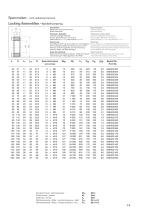
Spannsätze - nicht selbstzentrierend Locking Assemblies - Not-Self-centering Kennzeichen: Mittlere bis hohe Drehmomente Breite Toleranzen Toleranzen, Rauhtiefe: Höchste zulässige Rauhtiefe: Rt max 16µm (Ra 3 µm - Rz 13 µm) Wellentoleranz = h 11; Nabentoleranz = H 11 Zentrierung: Eine Selbstzentrierung ist bei dieser Art nicht gegeben. Die Rundlaufgenauigkeit der Verbindung ist von der Toleranz und Führungsbreite der Vorzentrierung zwischen Welle und Nabe abhängig. Axiale Verschiebung: Während des Schraubenanziehens erfolgt keine axiale Verschiebung der Nabe gegenüber der Welle. Characteristics:...
Open the catalog to page 9
Spannsätze - selbstzentrierend Locking Assemblies - Self-centering Kennzeichen: Mittlere bis hohe Drehmomente Kurze Montagezeiten Kostengünstige Anwendung Austauschbar mit WMH-Serie 298-002-… Toleranzen, Rauhtiefe: Höchste zulässige Rauhtiefe: Rt max 16µm (Ra 3 µm - Rz 13 µm) Wellentoleranz = h 8; Nabentoleranz = H 8 Tolerances, surface finish: maximum allowable surface finish: Rt max 16µm (Ra 3 µm - Rz 13 µm) shaft tolerance = h 8; hub tolerance = H 8 Axiale Verschiebung: Während des Schraubenanziehens erfolgt keine axiale Verschiebung der Nabe gegenüber der Welle. Characteristics: medium-high...
Open the catalog to page 10
Spannsätze - selbstzentrierend Locking Assemblies - Self-centering Kennzeichen: Mittlere bis hohe Drehmomente Kurze Montagezeiten Kostengünstige Anwendung Austauschbar mit WMH-Serie 298-002-… Toleranzen, Rauhtiefe: Höchste zulässige Rauhtiefe: Rt max 16µm (Ra 3 µm - Rz 13 µm) Wellentoleranz = h 8; Nabentoleranz = H 8 Axiale Verschiebung: Während des Schraubenanziehens erfolgt eine leichte axiale Verschiebung der Nabe gegenüber der Welle. Characteristics: medium-high torque limited installation time application economically advantageous interchangeable with WMH serie 298-002-… Tolerances, surface...
Open the catalog to page 11
Spannsätze - selbstzentrierend Locking Assemblies - Self-centering Kennzeichen: Hohe Drehmomente Kurze Montagezeiten Kostengünstige Anwendung Toleranzen, Rauhtiefe: Höchste zulässige Rauhtiefe: Rt max 16µm (Ra 3 µm - Rz 13 µm) Wellentoleranz = h 8; Nabentoleranz = H 8 Tolerances, surface finish: maximum allowable surface finish: Rt max 16µm (Ra 3 µm - Rz 13 µm) shaft tolerance = h 8; hub tolerance = H 8 Axiale Verschiebung: Während des Schraubenanziehens erfolgt keine axiale Verschiebung der Nabe gegenüber der Welle. Characteristics: high torque limited installation time application economically...
Open the catalog to page 12All WMH Srl catalogs and technical brochures
 Ballscrews & Accessories
24 Pages
 Lead Screws
20 Pages
 Couplings
18 Pages
 Preloaded Double Pinion
3 Pages
 Worm Gear Units
10 Pages
 Spur Gears
58 Pages
 sprocket
52 Pages
 Splined Shafts & Sleeves
4 Pages
 Screw Jacks
28 Pages
 Racks
Racks30 Pages
 New ! Master-Gears
5 Pages
 Chains
24 Pages
 Bevel Gears
12 Pages
 Belts
Belts46 Pages
 Ballscrews
24 Pages

- Screw jack
- Rack and pinion
- Straight-toothed sprocket wheel
- Ball screw
- Straight-toothed gear
- Helical gear rack
- Metal ball screw
- Rotating screw jack
- Lead screw
- Helical-toothed gear
- Precision ball screw
- Bevel gear
- Spur gear
- Hub gear
- Steel ball screw
- Safety nut screw jack
- Shaft gear
- Custom-made gear
- Spiral gear
- Stainless steel lead screw