


- Company
- Products
- Catalogs
- News & Trends
- Exhibitions
Wilo-Economy MHIE

Wilo-Economy MHIE
This document provides installation and operating instructions for the Wilo-Economy MHIE pump, originally in French with translations available. It is crucial for proper use and must be accessible at the installation site, complying with safety standards at the time of publication.
The pump is designed for pumping clear liquids in building, agriculture, and industry, but not suitable for Abyssinian wells.
- Max operating pressure: 10 bar
- Max suction pressure: 6 bar
- Temperature range: -15°C to +110°C (EPDM) / -15°C to +90°C (Viton)
- Ambient temperature: max +40°C
- Sound pressure level: 0/+3 dB(A)
Technicians and operators must read safety instructions before installation. Key symbols indicate general danger, electrical voltage danger, and handling notes. Personnel must be qualified, and unauthorized modifications are prohibited.
Check for transport damage upon receipt. Store the pump in a dry place if installation is delayed. Handle carefully to maintain geometry and alignment.
- Components include strainer-foot valve, suction valve, discharge valve, non-return valve, etc.
- The pump is centrifugal, multistage, and not self-priming.
- Motor is a 3-phase asynchronous motor with a speed variator.
- Accessories like IF-Modules, by-pass kits, and protection kits are available separately.
Two standard installation types are described. The pump should be installed in an accessible, frost-protected location. Hydraulic connections must be sealed properly, and electric connections should be made by qualified electricians.
Ensure compliance with applicable regulations. The motor-converter's electric characteristics must match the mains supply. Use power cables conforming to standards and ensure proper grounding.
Details on terminal connections for mains supply and inputs/outputs are provided, including instructions for sensor input, external setpoint input, and control input connections.
Describes connection terminals for interface modules like PLR and LON, designed to be twist-proof when connected to the converter. Outlines inputs and outputs for constant pressure and P.I.D. control connections.
Emphasizes safety, warning of death danger due to hazardous contact voltage from converter capacitors. Advises waiting five minutes after disconnecting supply voltage before intervention, ensuring all connections are voltage-free and properly earthed.
Explains control laws for input signals in constant pressure and P.I.D. control modes, detailing sensor signal ranges and implications of broken cables. Covers input of external frequency control in speed control mode.
Describes control elements, including setting with an encoder and switches for operation and service modes. Outlines display structure, focusing on access lock importance to prevent unauthorized changes.
Provides detailed menu navigation, including easy and expert modes for parameter settings. Explains adjustments for speed control, constant pressure, and P.I.D. control, emphasizing skilled technicians during commissioning.
Recommends preliminary rinsing for hygiene before using the pump with potable water. Details filling and degassing procedures, warning about dangers of operating the pump dry and precautions with hot water.
Before starting the pump, ensure the discharge valve is open. The pump should not operate at zero flow for more than 10 minutes with cold water or more than 5 minutes if temperature exceeds 60°C. A minimum flow of 10% of the pump's nominal flow is recommended to prevent vapor lock.
Faults should be addressed by qualified personnel. The converter is equipped with relays for centralized control. The SBM relay can be configured in three states: available transfer, run transfer, and power on transfer. The SSM relay activates upon detecting defects, stopping the pump until manual intervention.
Switch off equipment before maintenance. The pump and motor bearings are lubricated for life and require no additional lubrication. In case of prolonged stoppage, drain the pump if no frost risk. Replacement frequencies depend on operating conditions, with indicative lifetimes provided for components.
Provides a detailed error table listing possible faults, their causes, and remedies. Errors include pump overload, under/over voltage, missing supply phase, and motor overheating. Each error has specific remedies and waiting times before reset.
Errors should only be acknowledged once remedied. Skilled technicians should handle defects, and if in doubt, contact the manufacturer. The system displays error pages, and errors must be manually acknowledged if the auto-reset timer is inactive.
Spare parts should be ordered through approved technicians or Wilo after-sales service. Only original spare parts should be used to ensure proper pump function.
Includes a declaration of conformity with various European directives and standards, ensuring compliance with safety and environmental regulations.
Catalog excerpts
Wilo-Economy MHIE de Einbau- und Betriebsanleitung en Installation and operating instructions fr Notice de montage et de mise en service nl Inbouw- en bedieningsvoorschriften ru Инструкция по монтаж
Open the catalog to page 1
1. General About this document The language of the original operating instructions is French. All other languages of these instructions are transations of the original operating instructions. These installation and operating instructions are an integral part of the product. They must be kept readily available at the place where the product is installed. Strict adherence to these instructions is a precondition for the proper use and correct operation of the product. These installation and operating instructions conform to the relevant version of the product and the underlying safety standards...
Open the catalog to page 7
and knowledge, unless they have been given supervision or instruction concerning use of the appliance by a person responsible for their safety. Children should be supervised to ensure that they do not play with the appliance. If hot or cold components on the product/the unit lead to hazards, local measures must be taken to guard them against touching. Guards protecting against touching moving components (such as the coupling) must not be removed whilst the product is in operation. Leakages (e.g. from the shaft seals) of hazardous fluids (which are explosive, toxic or hot) must be led away so...
Open the catalog to page 8
• Weld-on (Steel) or screw-on (Stainless Steel) counterflange. • Non-return valves (with nose or spring ring when operating in constant pressure). • Strainer-foot valve. • Vibrationless sleeves. • Protection kit against dry-running • Sensor kit for pressure regulation (accuracy : ≤ 1 % ; use between 30 % and 100 % of the reading range). 5. Installation Two standard types. Fig. 1: pump in suction Fig. 2: pump in load on storage tank (item 9) or town water supply (item 10). Altitude 5.1 Montage - Install the pump in a place easy to reach, protected against frost and as close as possible from the...
Open the catalog to page 9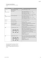
Connection terminal allocation • Loosen the screws and remove the converter cover. Allocation Mains connection voltage Earth connection Notes Three-phase current 3 ~ IEC38 Sensor input Type of signal: Voltage (0 - 10 V, 2 - 10 V) Input resistance: Ri ≥ 10 kΩ Type of signal: currrent (0 - 20 mA, 4 - 20 mA) Input resistance: Rb = 500 Ω Can be configured in the « Service » menu <5.3.0.0> IN2 External setpoint input (10V/20mA-terminal 7) Type of signal: Voltage (0 - 10 V, 2 - 10 V) Input resistance: Ri ≥ 10 kΩ Type of signal: currrent (0 - 20 mA, 4 - 20 mA) Input resistance: Rb = 500 Ω Can be configured...
Open the catalog to page 10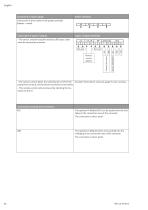
Power terminals Connect the 4 wires cable on the power terminals (phases + earth). Not used Remote control ON/OFF • The sensor, external setpoint and [ext.off] inputs cable must be necessarily screened. Inputs / outputs terminals Connection of inputs / outputs Connection to mains supply Example: Float switch, pressure gauge for dry-running… • The remote control allows the switching On or Off of the pump (free contact), this function has priority on the others. • This remote control can be removed by shunting the terminals (3 and 4). Connection terminals of the interface PLR The optional IF-Module...
Open the catalog to page 11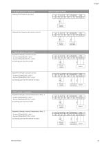
« Constant pressure » connection Inputs / outputs terminals Setting of the frequency by hand: 1 Remote control Setting of the frequency by external control: Remote control « Constant pressure » connection Regulation through a pressure sensor: • 2 wires ( [20mA/10V] / +24V ) • 3 wires ( [20mA/10V] / 0V / +24V ) and setting point by the encoder Remote control and setting point by the external set value Regulation through a pressure sensor: • 2 wires ( [20mA/10V] / +24V ) • 3 wires ( [20mA/10V] / 0V / +24V ) Remote control « P.I.D. control » connection Regulation through a sensor (temperature, flow,...):...
Open the catalog to page 12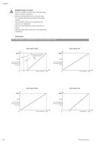
DANGER! Danger of death! Contact voltage hazardous due to the discharge of the converter capacitors. Before any intervention on the converter, wait for 5 minutes after disconnecting of the supply voltage. Check whether all electrical connections and contacts are voltagefree. Check the righ allocation of the connection terminals. Check the right earth connection of the pump and installation. Control laws IN1 : Input signal in « Constant pressure » and « P.I.D. control » mode Between 0 and 2 mA, cable is considered as broken Safety area in % of the range of measurement of the sensor in % of the...
Open the catalog to page 13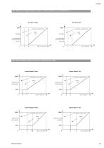
IN2 : Entrée de la consigne externe en mode « Pression constante » et « Contrôle P.I.D. » Area where converter stops Safety area Area where converter stops Safety area in % of the range of measurement of the sensor in % of the range of measurement of the sensor IN2 : Input of external frequency control in « Speed control » mode Area where converter stops Safety area Area where converter stops Safety area Safety area Area where converter stops Area where converter stops Safety area
Open the catalog to page 14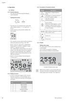
6.1.3 Description of standard symbols 6.1.1 Control elements The converter operates using the following control elements: Operating in « Speed control » mode. 2 Setting with encoder Operating in « Constant pressure » or « P.I.D. control » mode. Input IN2 activated (external setpoint). Access locked. When this symbol appears, current settings or measurements cannot be changed. Information displayed is only in reading. • The selection of a new parameter is done only with a simple rotation, « + » on right and « - » on left. • A short impulse on the encoder validates this new setting. Switch BMS...
Open the catalog to page 15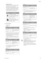
Navigation element • The arborescence of the menu allows to call the functions of the converter. A number is attributed to every menu and submenu. • The rotation of the encoder allows the scrolling of a same menu level (example 4000->5000). • Any blinking elements (value, menu number, symbol or icon) allow the choice of a new value, a new menu number or a new function. Symbol Description Only reading for the « Information » menu. • The « Information » menu displays measuring, device and operating data, (Fig. 12). <5.0.0.0> Position When the arrow appears: • An impulse on the encoder allows the...
Open the catalog to page 16All Wilo catalogs and technical brochures
 Wilo-HiPeri 1-4/5
36 Pages
 Wilo-Sub TWI 4-6
15 Pages
 Wilo-Yonos ECO BMS
28 Pages
 General Overview 2020
78 Pages