 Website:
Williams Milton Roy
Group: Milton Roy
Catalog excerpts
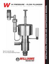
Also for use with older W, D & K Series Metering Pumps INSTALLATION, OPERATION AND MAINTENANCE MANUAL HI PRESSURE - FLOW PLUNGER
Open the catalog to page 1
This manual contains specific, comprehensive procedures to help users install, operate, and maintain the Williams Plunger Series of Pneumatic Metering Pump Assemblies consisting of a plunger pump and controller or a plunger pump, relay, and controller. For user convenience, the manual is divided into five sections: FUNCTIONAL DESCRIPTION Section 1.0 contains a physical operating sequence of the pumps. Section 2.0 contains specific proce- dures for installing the pumps and their various components including STARTUP, OPERATION, AND SHUTDOWN Section 3.0 contains procedures for setup,...
Open the catalog to page 2
Section 1.0: Functional Description 1.1 Physical Description The letters CP at the beginning of a pump assembly model number indicate that the model consists of a controller and pump. The letters CRP indicate that the model also has a relay. Controller types differ according to the pump model. • CP250K, CP125D and CP250D225 pump assemblies use the MK-II controller. • CP250D300 and CP500D pumps use the MK-VII controller. • All W series pumps--CP125W125, CP250W225, CP500W300. etc.--use the MK-X controller. Some W series pumps use relays which are of different sizes: • CRP500W400, CRP1000W400,...
Open the catalog to page 3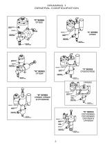
DRAWING 1 GENERAL CONFIGURATION
Open the catalog to page 4
CAUTION To prevent damage to the controller, always use a regulator between the supply and the controller when the air/gas supply pressure is more than the maximum rating of your controller. 1.2.1.2 Relay Supply Pressure: Relays, which require a separate air supply, operate with supply pressures of 50 psig (3.4 bar) minimum and 150 psig (10.3 bar) maximum. The supply pressure must be equal to or greater than the process pressure plus 200 psig divided by the pump amplification ratio. (See 1.2.1.1 above for definitions of process pressure and amplification ratio.) When using a...
Open the catalog to page 5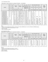
Max. Air Usage At Max. Volume Maximum Volume Maximum Pressure Gal./Hr Liter/Hr Amp Strokes Volume Ratio per per Minute stroke (SPM) (cc) Stroke length (Inch) Piston Diameter (Inch) Plunger Diameter (Inch) PNEUMATIC METERING PLUNGER PUMPS - W SERIES Approx. Shipping Weight Notes: 1. Minimum recommended stroke length is 1/8 inch for CP 125 to CRP500 and 1/4 inch for CP1000 to CRP2250 pumps. 2. Minimum recommended operating speed is 10 spm. 3. MK-X Controller. 4. MK-X Controller and Relay. Max. Air Usage At Max. Volume Maximum Volume Maximum Pressure Gal./Hr Liter/Hr Amp Strokes Volume Ratio...
Open the catalog to page 6
1.3.3 Pump Motor (Air Chamber) The motor forces the piston plunger to move alternately into and out of the pump chamber. When the controller sends the supply air/gas into the motor chamber through the nipple connector, the pressure on the U-cup and piston plunger overcomes the combined force of the process fluid pressure on the U-cup and piston plunger overcomes the combined force of the process fluid pressure on the U-cup, piston plunger, and plunger return spring and pushes the plunger into the fluid chamber. When the external controller exhausts the air/gas, the piston plunger return...
Open the catalog to page 7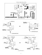
TYPICAL PUMP INSTALLATION DISCHARGE LINE Pressure Regulator High Pressure <™~f PNEUMATIC SUPPLY LIQUID CHEMICAL FEED CHECK VALVE CHECK VALVE SUCTION CHECK VALVE SUCTION CHECK VALVE
Open the catalog to page 8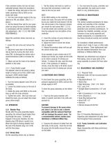
If the controller stroke rate has not been calibrated already, follow this procedure: 1. Rotate the stroke rate knob on the controller clockwise (CW) to ZERO on the stroke rate scale. 2. Turn the main air/gas supply to the regulator(s) to ON, and adjust. (See 3.1.1.1 above.) 3. Set the desired flow rate for your application by using the pump's stroke adjuster in combination with the controller's stroke rate adjustment. ( Ref. 1.2.2.5 FOR PUMP PERFORMANCE) 1. Set the stroke rate knob to a point on the scale that will product a stroke rate close to the one you want. 3. You may leave the pump,...
Open the catalog to page 9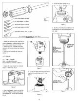
5/64" ALLEN WRENCH 1/4" DRIVE VB" ALLEN WRENCH V4" DRIVE 5/52* ALLEN WRENCH 1/4" DRIVE LOWER SEAT SPANNER TOOL 1/4" ORIVE MK-X SCREWDRIVER WITH 1/4" HEX SOCKET DRIVE 4. Lift out the spool spring. (Fig.4) 5. Use the correct blade screwdriver (1/8" for the MK-X) and unscrew the lower seat. 1. Rotate the oiler body 180° until the sili- cone oil bottle is in its normal upright posi- tion. Unscrew and remove the bottle. 2. Rinse the pump, controller, lubricator reservoir, and cap to remove any chemical 3. Unscrew the controller by hand and Disassemble the controller as follows: 1. Clamp the...
Open the catalog to page 10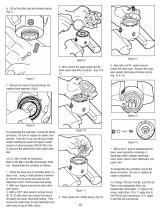
6. Lift out the pilot plug and exhaust spring. (Fig.7) Figure 9 4. Now remove the upper spool and the lower spool assembly (3 pieces). (Fig.10 & 11) Figure 12 6. Now with a 9/16" socket wrench loosen the lower seat. Remove the lower seat, gasket, pilot plug and lower spring. (Fig. 13 & 14) Figure 7 7. Remove the body O-ring that keeps the capillary tube separate. (Fig.8) Figure 8 To reassemble the controller, reverse the above procedure. Be sure to replace all rubber components. Flare the U-cup out with your finger before installing the spool and apply a small amount of silicone grease...
Open the catalog to page 11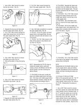
1. Use a 9/64" Allen wrench to remove the top cap screws. (Fig.15) Figure 15 2. Separate the top cap and data plate from the upper body section. (Fig.15) 3. Put a 7/64" Allen wrench through the upper body exhaust port, into the hole in the upper poppet stem. (Fig.16) 8. Put 7/64" Allen wrench through the hole in the upper poppet stem. (Fig.19) Figure 19 9. Use a flat blade screwdriver to unscrew the lower poppet stem. (Fig.19) 10. PO3-6S: Pull out the upper and lower poppet stems, and poppet body; the poppet stem connector bolt will remain in one of the stems. 11. PO3-6S: Put 7/64" Allen...
Open the catalog to page 12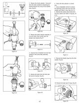
2. Remove the stroke adjuster. Unscrew it from the motor cylinder by loosening the knurled lock/set nut on top of the cylinder body. (Fig.26) 6. Clamp the fluid cylinder in a bench vise. 7. Use an adjustable wrench to remove the discharge check valve from the fluid cylinder and Teflon O-ring. (Fig.30 & 31) 8. Remove the suction check valve from the fluid cylinder and Teflon O-ring.(Fig. 30 & 31) Figure 26 Figure 30 3. Remove the piston plunger assembly Ucup and motor return spring, plus the plunger seal retainer.(Fig.27) Figure 27 Figure 24 4. Unscrew the oil chamber from the fluid cylinder...
Open the catalog to page 13All Williams Milton Roy catalogs and technical brochures
-
31049 MKVII PL RK
1 Pages
-
31025 5-2012 P125V V&X PL RK
2 Pages
-
30956 V Series
32 Pages
-
P2250 Parts List
1 Pages
-
P1500 Parts List 39288
2 Pages
-
PCV125-AL
1 Pages
-
APU-XP
1 Pages
-
WPC-9001-GP XP Control Units
2 Pages
-
MKXII Controller
2 Pages
-
Wilroy Brochure
6 Pages
-
V series Brochure
12 Pages
-
W-Series Brochure
8 Pages
-
Conversion Kit
4 Pages
-
Wilroy IOM
20 Pages
Archived catalogs
-
Williams V Dual Seal #30950
12 Pages


