
- Catalogs
- Williams Milton Roy
- 30956 V Series

30956 V Series

30956 V Series
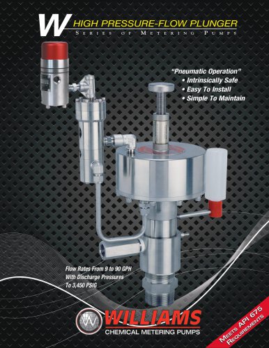
- Physical Description: Pump models are identified by codes indicating the presence of a controller (C), pump (P), and relay (R). Pneumatic relays are necessary for pumps with larger drive cylinder diameters.
- Controller: Manages air/gas supply using a capillary tube and needle valve, with a sliding spool mechanism for flow control.
- Relays: Function as pilot-operated servo valves, with models differing based on motor return spring presence.
- Pumps: Comprise a body, fluid chamber, and motor cylinder, with check valves for fluid flow direction control.
- Controllers and Relays: Require separate air/gas supplies, operating between 35 psig and 150 psig. Multiplexing pumps can enhance fluid flow rates.
- Pumps: Performance is detailed in flow pressure tables, indicating maximum volume, stroke length, and discharge pressure.
- Installation: Guidelines include pump assembly, typical setups, and use of supply reservoirs and relief valves.
- Startup, Operation, and Shutdown: Procedures for starting, operating, and shutting down pumps, including storage recommendations.
- Maintenance: Covers disassembly, assembly, preventive maintenance, and troubleshooting tips.
- Details on ordering parts and repair kits for controllers and relays.
- Graphs show the relationship between air/gas supply pressure and discharge pressure, aiding in determining optimal flow range and necessary air pressure for desired pump performance.
Detailed specifications for pump models, including discharge pressure, flow rate (GPH), and air pressure (PSI). Stroke length is consistently 100%, and plunger speed is 45 SPM.
Performance Flow Curves:
Graphs illustrate the relationship between discharge pressure and flow rate under different air/gas pressures.
Material Selection:
Guidelines for selecting plunger and seal materials based on chemical compatibility and hardness. Ceramic is recommended for its hardness and chemical inertness. Various seal materials are discussed, each with specific temperature and pressure ranges.
General Operating Sequence:
Describes the operation of the MK XII Controller and relays, detailing how high-pressure air/gas interacts with the system.
Installation Recommendations:
Recommends installing pressure regulators, dryers, dump valves, isolation valves, check valves, inlet filters, and flow meters for optimal performance.
Specifies a net positive suction head limit of 100 psig. Pumps are not recommended for suction lift positions. A safety relief valve is unnecessary if downstream piping can withstand maximum pressure.
Startup, Operation, Shutdown, and Storage
Startup: Ensure primary air/gas supply is off and pressure regulators are set to zero. Air/gas supply pressure must be sufficient to produce a pump discharge pressure 200 psi higher than process pressure.
Operation: Set stroke rate using the controller's knob and adjust as necessary. Bleed air trapped in the pump chamber.
Shutdown and Storage: Set pressure regulators to zero and turn off air/gas supply. For long-term storage, remove the pump, flush it, and store it dry.
Procedures for disassembly and assembly of the controller, pump, and check valves, with preventive and corrective maintenance tips. Replace any seals removed during maintenance.
Controllers: Steps for disassembling the Mark XII Controller.
Relays: Instructions for disassembling PO3-6S and PO4-6S relays.
Includes figures illustrating disassembly processes for various components.
Changing Plunger Seals
- Disassembly: Unscrew pump body to access primary seal. Remove old seals carefully.
- Reassembly: Install new seals, apply grease, and ensure proper torque values.
Complete Pump Rebuild
- Disassemble pumps using specific tools, keeping parts together.
- Reassemble by aligning parts correctly and using specified torque values.
Section 4.2.5: Discharge Check Valves
- Disassemble and reassemble using appropriate tools, inspecting and replacing worn parts.
Section 4.2.6: Suction Check Valves
- Similar process as discharge check valves, with attention to O-ring placement.
Section 4.3: Preventive Maintenance
- Weekly: Check for leaks and loose fittings.
- Monthly: Add silicone oil to the system.
- Every Six Months: Inspect and replace seals, check for wear.
- Annually: Disassemble and inspect check valves, replace worn parts.
Clean all surfaces with an approved solvent and dry with compressed air during disassembly. Use a solvent compatible with the process fluid.
Proper Pump Use: Ensure correct use by checking air/gas supply, pressure regulator, tube size, and other factors.
Proper Amount of Use: Determine if the pump is overworked using the amplification ratio and process pressure.
Troubleshooting Guide: Solutions for common problems, such as non-oscillating controllers and relay issues, are provided.
Provides part numbers and repair kit references for controllers and relays used in various pump models.
Catalog excerpts

DUAL SEAL PLUNGER S INSTALLATION, OPERATION, AND MAINTENANCE MANUAL
Open the catalog to page 1
DUAL SEAL PLUNGER Series of Metering Pumps PART NUMBER DESIGNATION CR P1000V800 A PE C: Controller CR: Controller - Relay S: Solenoid Valve SR: Solenoid Valve - Relay Plunger Material A: 17-4 ph B: 316 SS CR: Ceramic Seal Material NOTE:(,) The 400, 600 and 800 motor cylinders are only available with the CR (controller-relay) or SR (solenoid-relay) control methods. PE: Polyethylene (UHMW) TC: Teflon® Composite TG: Teflon® Graphite V: Viton® BR: Buna N K: Kalrez® EPR: Ethylene Propylene
Open the catalog to page 2
Section Description Page 5.0 PARTS LIST AND REPAIR KIT ORDERING REFERENCE 26 5.1 Controller Part Lists and Repair Kits 26 5.2 Relay Part Lists and Repair Kits
Open the catalog to page 3
CP500V300. The letters CRP mean that the model also has a relay (R). For example: CRP500V400, CRP750V400, CRP1000V400, CRP1000V600, and CRP1000V800. SECTION 1.0: FUNCTIONAL DESCRIPTION 1.1 PHYSICAL DESCRIPTION Some pumps use different relay sizes: • CRP500V400, CRP750V400, CRP1000V400, and CRP1000V600 pumps use the PO3-6S relay. • CRP1000V800 pump uses the PO4-6S relay. The letters CP at the beginning of a pump assembly model number mean that the model consists of a controller (C) and pump (P) For example: CP125V125, CP250V225, CP250V300, CP500V225, and 1.1.1 Controller The controller, consisting...
Open the catalog to page 4
entering pump or relay, and opens the vent to let it exhaust. The spool then returns to its highest position and repeats the cycle. 1.1.2 Relays A relay is a pilot operated servo valve. Air/gas pressure from a controller forces a piston and one or more attached poppet valves to move. Then, when the controller removes the pressure, a spring forces both the piston and poppet valve(s) in the reverse direction. Relay models differ in operation. The PO3-6S relay has one poppet valve that connects the supply air/gas to the pump and blocks the exhaust when the controller applies air/gas pressure to...
Open the catalog to page 5
1.2.1 Controllers and Relays Controllers and relays will require separate supply sources, and fortunately will operate with air or any gas, such as carbon dioxide, nitrogen or natural gas. WARNING: TO PREVENT INJURY, MAKE SURE THAT ANY FLAMMABLE GAS SUCH AS NATURAL GAS IS PROPERLY VENTED FOR SAFETY. CAUTION: If the gas could possibly damage the standard elastomeric material, please contact your distributor or Williams Instrument Incorporated for advice. To increase the process fluid flow rate, two or more pumps can be multiplexed: their inlets and outlets connected in parallel. 1.2.1.1 Controller...
Open the catalog to page 6
1.2.2.2 Using The Graphs* Use the following Performance Flow Curves* in order to: 1) Determine the flow capability of the pump you have selected. If you have sized the pump too close to the upper or lower stroke rate limit, you may wish to change to a different pump size. Of course you can also change your flow for a given stroke rate by adjusting the stroke length. Example: These Settings Will Produce The Same Pump Flow Rate STROKE RATE 10 20 40 2) Determine the air pressure necessary to provide the desired pump discharge pressure. A) The flow curves show the maximum flow/pressure limit of the...
Open the catalog to page 7
Performance Flow Curves STROKE LENGTH: 100% • PLUNGER SPEED: 45 SPM STROKE LENGTH: 100% • PLUNGER SPEED: 45 SPM STROKE LENGTH: 100% • PLUNGER SPEED: 45 SPM AIR/GAS PRESSURE PSIG AIR/GAS PRESSURE PSIG AIR/GAS PRESSURE PSIG CP250V300 Discharge Pressure PSI gph Air Pressure PSI
Open the catalog to page 8
Performance Flow Curves (cont.) STROKE LENGTH: 100% • PLUNGER SPEED: 45 SPM STROKE LENGTH: 100% • PLUNGER SPEED: 45 SPM AIR/GAS PRESSURE - PSIG AIR/GAS PRESSURE - PSIG AIR/GAS PRESSURE PSIG CRP500V400 Discharge Pressure PSI Gph Air Pressure PSI
Open the catalog to page 9
Performance Flow Curves (cont.) STROKE LENGTH: 100% • PLUNGER SPEED: 45 SPM AIR/GAS PRESSURE - PSIG STROKE LENGTH: 100% • PLUNGER SPEED: 45 SPM & 35 SPM @ 150 PSIG STROKE LENGTH: 100% • PLUNGER SPEED: 45 SPM & 35 SPM @ 150 PSIG AIR/GAS PRESSURE - PSIG AIR/GAS PRESSURE - PSIG STROKE LENGTH: 100% • PLUNGER SPEED: 45 SPM AIR/GAS PRESSURE - PSIG Discharge Pressure PSI gph Air Pressure PSI
Open the catalog to page 10
8 1.2.2.3 Plunger & Seal Material 1.2.2.3.1 Plunger Material Selection The materials available vary in hardness and chemical compatibility. We offer three materials based on our many years of industry experience with various chemicals. Hardness is a key property when selecting the proper plunger material. Our experience has shown that the harder plunger materials not only provide longer plunger life, they also provide greater seal life. A hard plunger is a must when pumping a chemical that is prone to crystallization or if the chemical is contaminated. Of course both of the preceding conditions...
Open the catalog to page 11
1.3 GENERAL OPERATING SEQUENCE 1.3.1.1 MK XII Controller The spool spring forces the spool upward to its highest position and unseats the top of the pilot plug from the upper seat. The exhaust spring forces the pilot plug upward and seats it on the lower seat. This blocks the air/gas exhaust port. When high pressure air/gas enters the supply port, it passes around and through the spool and past the open upper seat to the motor cylinder port. High pressure air/gas passes through the control passage in the controller, past the valve stem, and into the valve body upper chamber which causes pressure...
Open the catalog to page 12
When the controller sends a pilot pulse, the high pressure gas on top of the relay piston overcomes the piston spring force and pushes the piston and two poppets assemblies downward. The piston and two poppets assemblies move down until the O-ring on the bottom of the upper poppet presses against the middle body section and the O-ring on the bottom of the lower poppet presses against the lower body section. The upper poppet O-ring seals the number one pump port from the supply port; the space above provides a path between the number one pump and exhaust ports. The lower poppet O-ring seals the...
Open the catalog to page 13
2.3 TYPICAL INSTALLATION Below you will find a schematic for a typical “V” plunger pump installation. The key ingredients for a successful installation are: 1: Clean, dry regulated air for the controller 2: A flooded inlet supply 3: An inlet filter 4: A rate setting gauge 5: A line check valve at the point of injection 6: Isolation valves for maintenance on each component. AIR/GAS DRYER PRESSURE REGULATOR DUMP VALVE DUMP VALVE PUMP AIR/GAS SUPPLY PUMP & CONTROLLER RATE SETTING GAUGE AIR/GAS DRYER PRESSURE REGULATOR RATE SETTING GAUGE AIR/GAS SUPPLY CHEMICAL SUPPLY AUTO CONTROL MANUAL CHECK VALVE...
Open the catalog to page 14All Williams Milton Roy catalogs and technical brochures
 W-Series Brochure
8 Pages
 31049 MKVII PL RK
1 Page
 31025 5-2012 P125V V&X PL RK
2 Pages
 P2250 Parts List
1 Page
 P1500 Parts List 39288
2 Pages
 PCV125-AL
1 Page
 APU-XP
1 Page
 WPC-9001-GP XP Control Units
2 Pages
 W Series Pump IOM
25 Pages
 MKXII Controller
2 Pages
 Wilroy Brochure
6 Pages
 V series Brochure
12 Pages
 W-Series Brochure
8 Pages
 Conversion Kit
4 Pages
 Wilroy IOM
20 Pages

Archived catalogs
 Williams V Dual Seal #30950
12 Pages

