
- Catalogs
- WICK ELECTRONIC COMPANY LIMITED
- WICK SENSOR GENERAL CATALOG

- Products
- Catalogs
- News & Trends
- Exhibitions
WICK SENSOR GENERAL CATALOG

WICK SENSOR GENERAL CATALOG
- Voltage Range: 10-30VDC, 10-55VDC, 5-36VDC
- Switching Frequency: Up to 1KHz
- Response Time: 0.2ms to 1ms depending on the model
- Protection Category: IP67
- Operating Temperature: -25°C to +70°C
- Housing Material: Stainless steel, nickel-plated brass, and PBT
- Connection Types: M8 and M12 connectors, and cable options
- Ripple: <10%
- No Load Current: <10mA
- Max Load Current: 200mA
- Leakage Current: <0.01mA
- Voltage Drop: <2.0V
- Switching Hysteresis: <15%(Sr)
- Repeat Accuracy: <1.0%(Sr)
- Temperature Drift: <10%(Sr)
- Short Circuit Protection
- Overload Trip Point
- LED Indicators for status
- Housing Material: Nickel Plated Brass or Plastic
- Tolerance: ±10%(Sr)
- Short Circuit Protection: Yes
- Electric Protections: Yes
- Sensing Object: Varies by model
- Supply Voltage: 10-30VDC (±10%) or 24-240VDC (±10%)
- No Load Current: ≤30mA or ≤5mA
- Max. Load Current: 150mA or 200mA
- Voltage Drop (Sensor ON): ≤2.5V
- Response Time: 1ms or 15ms
- Switching Hysteresis: <10%(Sr)
- Emitting Element: Red (660nm) or Infrared (880nm)
- Protection Category: IP67
- Operating Temperature: -25 to +55°C
- Output: PNP or NPN, AC non-contact (MOSFET Output)
- Output Operation: Light On & Dark On, Light On or Dark On
- Ambient Humidity: 35% - 85% RH
- Light Immunity: >10,000 Lux
- Weight: Approx. 60g to 120g depending on model
- Wiring diagrams are provided for both cable and connector versions, detailing connections for NPN and PNP outputs.
- Sensitivity adjustment is available via a trimmer for certain models.
- Q50 Series: Operates on 12-240VDC/24-240VAC, with a sensing range of 300mm to 2000mm, IP65 rated.
- Q60 Series: Operates on 10-30VDC, with ranges up to 10 meters, IP65 rated.
- Q80 Series: Available in 10-30VDC and 12-240V AC/DC versions, with a sensing range from 250mm to 50 meters, IP67 rated.
- U Series: Designed with an IR emitter and detector, suitable for high sensitivity applications.
Catalog excerpts

WiGk sensor ULTRA MINI & ULTRA SHORT Ultra-Mini Inductive Proximity Sensor Compact Precise Fast Response Ultra-Short Inductive Proximity Sensor Compact Precise Fast Response .small, with great future.
Open the catalog to page 2
TABLE OF CONTENT Page Selection Guide For Proximity Sensor ………………………………………………… 001 General Information For Inductive Proximity Sensor ……………………………. 002~008 General Information For Capacitive Proximity Sensor ………………………….. 009~012 Wiring Diagram For Proximity Sensor …………………………………………….. 013~015 Ultra-Mini Inductive Proximity Sensor …………………………………………….. 016~024 Ultra-Short Inductive Proximity Sensor …………………………………………… 025~035 DC Inductive Proximity Sensor ……………………………………………...…… 036~056 DC 2wire / 4wire Inductive Proximity Sensor …………………………………….. 057~068 Extended Range Inductive Proximity Sensor ……………………………………....
Open the catalog to page 3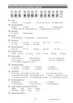
SELECTION GUIDE FOR PROXIMITY SENSOR 1 2 3 4 5 6 7 8 9 9 10 11 12 I 1 2 3 B S - M 12 02 P - A 1 V N 2 Type I: Inductive 4 5 6 7 C: Capacitive W: Weld Field Immune Housing Material P: Plastic B: Brass V: Stainless Steel Tube + Stainless Steel Face Mounting S: Shielded 13 M: Magnet Sensor T: PTFE S: Stainless Steel H: Stainless Steel Tube + ZrO2 Face N: Non-shielded Shape M: Threaded Barrel Dimension 3: 3mm 12: 12mm 8 S: Smooth Barrel 4: 4mm 18: 18mm 5: 5mm 30: 30mm C: DC 2-wire 6.5: 6.5mm ... 8: 8mm 02: 2mm Sensing Distance 01: 1mm 0.6: 0.6mm Output Function P: PNP N: NPN Q: Square Housing 05:...
Open the catalog to page 4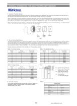
GENERAL INFORMATION FOR INDUCTIVE PROXIMITY SENSOR 1. Inductive Proximity Sensor Inductive Proximity Switches operate by using an L/C resonant oscillator which generates, with the aid of a coil located in the open pot core, a high frequency alternating electromagnetic field. This field emerges from the active face of the switch. When an electrically conductive material (for example a steel plate) moves into the electromagnetic field, an induced eddy current occurs. This eddy current extracts energy from the L/C resonant circuit in the switch, and produces a reduction in the oscillation amplitude....
Open the catalog to page 5
GENERAL INFORMATION FOR INDUCTIVE PROXIMITY SENSOR Shielded construction includes a metal band which surrounds the ferrite Non-shielded sensors do not have this metal band, therefore they core and coil arrangement. This helps to direct the electro-magnetic can be side sensitive. field to the front of the sensor. Shielded Sensor Non-shielded Sensor 5. Sensor response curve (See Fig.3) Hystersis is the travel of the target between the "switch-on" point and the "switch-off" point. This distance is required to allow the switch to properly detect the target, and reduces the possibility of false trips....
Open the catalog to page 6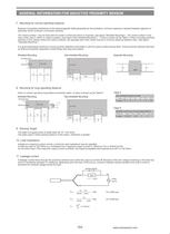
GENERAL INFORMATION FOR INDUCTIVE PROXIMITY SENSOR 7. Mounting for normal operating distance Because of possible interference of the electromagnetic fields generated by the oscillators, minimum spacing is required between adjacent or opposing "active surfaces" of proximity switches. The "active surface " may be flush with the metal in which the switch is mounted, (see figure "Shielded Mounting"). The "active surface" must have a free zone in which no metal is present, (see figure "Non-shielded Mounting".). Y value is shown as the Table 5. When mounting proximity switches in this manner where...
Open the catalog to page 7
GENERAL INFORMATION FOR INDUCTIVE PROXIMITY SENSOR If continuous curent flowing through the load Is less than 10mA, the proximity switch will malfunction. Connect the bleeder resistor parallel to the load in order to increase the current flowing through the load to more than 10mA. This allows the SCR in the circuit to operate reliably, and decrease the remaining voltage across the load. bleeder resistor Variation in sensing distance for successive operations under specified conditions (specified sensing range, temperature at 23±5"C, humidity £90%, specified operating voltage, circyle is 8 hours)....
Open the catalog to page 8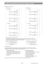
GENERAL INFORMATION FOR INDUCTIVE PROXIMITY SENSOR Parallel connection Seríes connection Logic functions with DC proximity sensors: Self-contained proximity sensors can be wired in series or parallel to perform such logic functions as AND, OR, NAND, NOR. The wiring diagrams show the connection of four sensors with npn and pnp outputs. Take into account the accumulating voltage drop per sensor added in the series-string. Parallel-connection : Parallel-connection : N.O. sensors: OR Function (any one sensor N.C. sensors: NAND Function (all sensors Series-connection: Parallel-connection: The International...
Open the catalog to page 9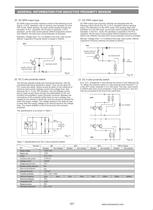
GENERAL INFORMATION FOR INDUCTIVE PROXIMITY SENSOR DC NPN output proximity switches consist of the following circuit (Fig.9). In N.O. operation, with no sensing, the transistor is in the OFF mode. When sensing, the load current passes through the transistor. In N.C. operation, the function is opposite. In N.O. operation, as the load current passes 200mA (capacitive version over 300mA), the load short circuit protection is activated. Remarks: Voltage drop <1V, it is tested in the max. load current, 200mA. Capacitive Proximity Switch is tested in 300mA. SHORT CIRCUIT 22. DC 2 wire proximity switch...
Open the catalog to page 10All WICK ELECTRONIC COMPANY LIMITED catalogs and technical brochures
 Wick Proximity Sensors
2 Pages
 Light Curtain - Wick Sensors
12 Pages


- Cylindrical proximity sensor
- IP67 proximity sensor
- Light barrier
- Multibeam light curtain
- Through-beam light curtain
- Threaded proximity sensor
- Safety light curtain
- Stainless steel proximity sensor
- M12 proximity sensor
- Brass proximity sensor
- M18 proximity sensor
- M8 proximity sensor
- M30 proximity sensor
- Non-contact proximity sensor
- 3-wire proximity sensor
- Proximity sensor with switching function
- Miniature proximity sensor