
Catalog excerpts

Technical Information OMSW with brake nose orbital motors
Open the catalog to page 1
accept no responsibility for possible errors in catalogues, brochures, and other printed material. WHITE reserves the right to alter its products without notice. This also applies to products already on order provided that such alterations can be made subsequent changes being necessary in specifications already agreed. All trademarks in this material are the property of the respective companies. WHITE and the WHITE logotype are trademarks of WHITE Drive Motors & Steering LLC and WHITE Drive Motors and Steering Sp. z o.o.. All rights reserved.
Open the catalog to page 2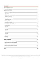
Contents Chapter 1 Product overview _______________________________________________________________ 4 Speed, torque and output _________________________________________________________________________ 5 Chapter 2 Technical data _________________________________________________________________ 6 Technical data for OMSW__________________________________________________________________________ 7 Max. pressure ___________________________________________________________________________________________ 8 Max. permissible shaft seal pressure...
Open the catalog to page 3
Chapter 1 General Information Topics: • Speed, torque and output WHITE can accept no responsibility for possible errors in catalogues, brochures, and other printed material. WHITE reserves the right to alter its products without notice. This also applies to products already on order provided that such alterations can be made without subsequent changes being necessary in specifications already agreed. All trademarks in this material are the property of the respective companies. WHITE and the WHITE logotype are trademarks of WHITE Drive Motors & Steering LLC and WHITE Drive Motors and...
Open the catalog to page 4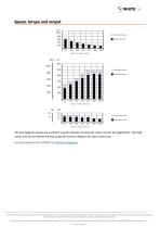
Speed, torque and output Intermittent values Continuous values Intermittent values Continuous values Intermittent values Continuous values The bar diagrams above are useful for a quick selection of relevant motor size for the application. The final motor size can be determined by using the function diagram for each motor size. Function diagrams for OMSW see Function diagrams. WHITE can accept no responsibility for possible errors in catalogues, brochures, and other printed material. WHITE reserves the right to alter its products without notice. This also applies to products already on order...
Open the catalog to page 5
Chapter 2 Technical data Topics: • • • • • • • Technical data for OMSW Max. permissible shaft seal pressure Oil flow in drain line Direction of shaft rotation Function diagrams Shaft version Port thread versions WHITE can accept no responsibility for possible errors in catalogues, brochures, and other printed material. WHITE reserves the right to alter its products without notice. This also applies to products already on order provided that such alterations can be made without subsequent changes being necessary in specifications already agreed. All trademarks in this material are the...
Open the catalog to page 6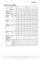
Technical data for OMSW Type Motor size Geometric displacement Maximum speed min [rpm] Maximum torque int. Maximum pressure drop peak 2) Maximum oil flow Maximum starting pressure with unloaded shaft Minimum starting torque l/min cont. [US gal/min] int.1) bar [psi] at maximum press drop cont. N•m [lbf•in] at maximum press drop int.1) N•m [lbf•in] Table 1 Technical data for OMSW WHITE can accept no responsibility for possible errors in catalogues, brochures, and other printed material. WHITE reserves the right to alter its products without notice. This also applies to products already on...
Open the catalog to page 7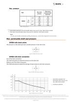
Max. pressure Max inlet pressure cont. OMSW Max return pressure with drain line Intermittent operation: the permissible values may occur for max. 10% of every minute. Peak load: the permissible values may occur for maximum 1% of every minute. Note: For max. permissible combination of flow and pressure, see function diagram for actual motor. Max. permissible shaft seal pressure OMSW with check valves The pressure on the shaft seal never exceeds pressure in the return line Figure 4 OMSW with check valves OMSW with drain connection Use of the drain connection: The shaft seal pressure equals...
Open the catalog to page 8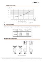
Pressure drop in motor Figure 7 Pressure Drop in OMSW The curve applies to an unloaded motor shaft and an oil viscosity of 35 mm2/s [165 SUS] Oil flow in drain line The table below shows the max. oil flow in the drain line at a return pressure less than 5-10 bar [75-150 psi]. Pressure Viscosity Oil flow in drop drain line bar mm2/s l/min [psi] [SUS] [US gal/min] Pressure drop bar [psi] Oil flow in drain line l/min [US gal/min] Table 3 Oil flow in drain line Direction of shaft rotation Figure 8 direction of shaft rotation WHITE can accept no responsibility for possible errors in catalogues,...
Open the catalog to page 9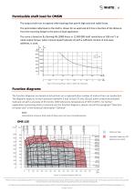
Permissible shaft load for OMSW The output shaft runs in tapered roller bearings that permit high axial and radial forces. The permissible radial load on the shaft is shown for an axial load of 0 N as a function of the distance from the mounting flange to the point of load application. The curve is based on B10 Bearing life (2000 hours or 12 000 000 shaft revolutions at 100 min-1) at rated output torque, when mineral-based hydraulic oil with a sufficient content of anti-wear additives, is used. Figure 9 Mounting flange: Wheel / Shaft: All shaft types Function diagrams The function diagrams...
Open the catalog to page 10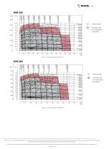
Continuous range Intermittent range (max. 10% operation every minute) Figure 11 Function diagram OMS 160 Continuous range Intermittent range (max. 10% operation every minute) Figure 12 Function diagram OMS 200 WHITE can accept no responsibility for possible errors in catalogues, brochures, and other printed material. WHITE reserves the right to alter its products without notice. This also applies to products already on order provided that such alterations can be made without subsequent changes being necessary in specifications already agreed. All trademarks in this material are the property...
Open the catalog to page 11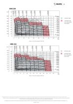
Continuous range Intermittent range (max. 10% operation every minute) Figure 13 Function diagram OMS 250 Continuous range Intermittent range (max. 10% operation every minute) Figure 14 Function diagram OMS 315 WHITE can accept no responsibility for possible errors in catalogues, brochures, and other printed material. WHITE reserves the right to alter its products without notice. This also applies to products already on order provided that such alterations can be made without subsequent changes being necessary in specifications already agreed. All trademarks in this material are the property...
Open the catalog to page 12All White Drive Products catalogs and technical brochures
-
RS
36 Pages
-
HP 30
42 Pages
-
VIS 40, 45
65 Pages
-
OMS
53 Pages
-
2012 Product Catalog
259 Pages
-
FD
6 Pages
-
SB
7 Pages
-
BK series 913
4 Pages
-
D9
14 Pages
-
DT
18 Pages
-
DR
23 Pages
-
RE
27 Pages
-
CE
21 Pages
-
WS
26 Pages
-
HB/HK
22 Pages
-
WG
22 Pages
-
WR
18 Pages
-
RS
15 Pages
-
WP
18 Pages
-
WD
14 Pages
-
WM
8 Pages
-
HB
20 Pages
Archived catalogs
-
Product Catalog
258 Pages
-
RS
16 Pages
-
WS
22 Pages
-
FD
6 Pages
-
BK series 910
4 Pages
-
DT
20 Pages
-
RG Series
32 Pages
-
White Hydraulics - Drive products
204 Pages


