- Catalogs
- White Drive Motors And Steering
- S10 | S20 Technical Information
S10 | S20 Technical Information
1 /39Pages

S10 | S20 Technical Information
1 /39Pages
Catalog excerpts

accept no responsibility for possible errors in catalogues, brochures, and other printed material. WHITE reserves the right to alter its products without notice. This also applies to products already on order provided that such alterations can be made subsequent changes being necessary in specifications already agreed. All trademarks in this material are the property of the respective companies. WHITE and the WHITE logotype are trademarks of WHITE Drive Motors & Steering LLC and WHITE Drive Motors and Steering Sp. z o.o.. All rights reserved.
Open the catalog to page 1
accept no responsibility for possible errors in catalogues, brochures, and other printed material. WHITE reserves the right to alter its products without notice. This also applies to products already on order provided that such alterations can be made subsequent changes being necessary in specifications already agreed. All trademarks in this material are the property of the respective companies. WHITE and the WHITE logotype are trademarks of WHITE Drive Motors & Steering LLC and WHITE Drive Motors and Steering Sp. z o.o.. All rights reserved.
Open the catalog to page 2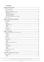
WHITE can accept no responsibility for possible errors in catalogues, brochures, and other printed material. WHITE reserves the right to alter its products without notice. This also applies to products already on order provided that such alterations can be made without subsequent changes being necessary in specifications already agreed. All trademarks in this material are the property of the respective companies. WHITE and the WHITE logotype are trademarks of WHITE Drive Motors & Steering LLC and WHITE Drive Motors and Steering Sp. z o.o.. All rights reserved.
Open the catalog to page 3
WHITE can accept no responsibility for possible errors in catalogues, brochures, and other printed material. WHITE reserves the right to alter its products without notice. This also applies to products already on order provided that such alterations can be made without subsequent changes being necessary in specifications already agreed. All trademarks in this material are the property of the respective companies. WHITE and the WHITE logotype are trademarks of WHITE Drive Motors & Steering LLC and WHITE Drive Motors and Steering Sp. z o.o.. All rights rese
Open the catalog to page 4
Chapter 1 General Information Topics: • • • Description and Advantages Hydraulic Circuit Explanation Valve Description WHITE can accept no responsibility for possible errors in catalogues, brochures, and other printed material. WHITE reserves the right to alter its products without notice. This also applies to products already on order provided that such alterations can be made without subsequent changes being necessary in specifications already agreed. All trademarks in this material are the property of the respective companies. WHITE and the WHITE logotype are trademarks of WHITE Drive Motors...
Open the catalog to page 5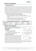
The Steering control unit (SCU) is fully fluid linked. This means there is no mechanical connection between the steering unit, the pump and the steering cylinders. The unit consists of a manually operated directional control servo valve and feedback meter element in a single body. It is used principally for fluid linked power steering systems, but it can be used for some servo-type applications or any application where visual positioning is required. The close coupled, rotary action valve performs all necessary fluid directing functions with a small number of moving parts. The manually actuated...
Open the catalog to page 6
7 The following special considerations should be addressed when applying power beyond steering: • Auxiliary valves (connected to PB) must be open center type. Slight bump or kick may be felt in steering wheel when auxiliary functions are activated during steering operations. Pump flow not used for steering is available at power beyond (PB) outlet, except at steering stops where total pump flow goes over the system relief valve. Avoid auxiliary functions that require constant flow while steering. Flow is only directed to the tank port when steering is operated. Avoid systems where return flow...
Open the catalog to page 7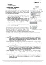
Construction Industry Neutral Circuits: Load Sensing Load Sensing Circuits Load sensing power steering uses conventional or load sensing power supplies to achieve load sensing steering. The use of a load sensing steering unit and a priority valve in a normal power steering circuit offers the following advantages: • Provides smooth pressure compensated steering be- cause load variations in the steering circuit do not affect axle response or maximum steering rate. Provides true power beyond system capability by splitting the system into two independent circuits. Pressure transients are isolated...
Open the catalog to page 8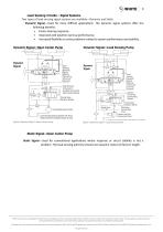
9 Load Sensing Circuits – Signal Systems Two types of load sensing signal systems are available—Dynamic and Static. Dynamic Signal—Used for more difficult applications. The dynamic signal systems offer the following benefits: • Faster steering response. • Improved cold weather start-up performance. • Increased flexibility to solve problems related to system performance and stability. Dynamic Signal—Open Center Pump Dynamic Signal—Load Sensing Pump Figure 6 Dynamic Signal—Open Center Pump Figure 7 Dynamic Signal—Load Sensing Pump Static Signal—Open Center Pump Static Signal—Used for conventional...
Open the catalog to page 9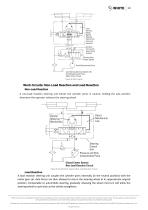
Control Unit Circuit with Open Center Priority Valve (Static Signal) Fixed Displacement Pump Load Sensing Steering System with Fixed Displacement Pump (Open Center Circuit) Figure 8 Static Signal Work Circuits: Non-Load Reaction and Load ReactionNon-Load Reaction A non-load reaction steering unit blocks the cylinder ports in neutral, holding the axle position whenever the operator releases the steering wheel. Mechanism Direct Mechanical Link Steering Control Pressure and F owCompensated Pump Closed Center System Non-Load Reaction Circuit Figure 9 Closed Center System (Non-Load Reaction Circuit)...
Open the catalog to page 10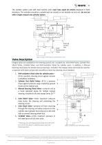
11 The cylinder system used with load reaction units must have equal oil volume displaced in both directions. The cylinders should be a parallel pair (as shown) or one double rod end unit. Do not use with a single unequal area cylinder system. Figure 10 Open Center System Load Reaction Circuit Valve Description Integral valves are available for the steering control unit. Included are: Inlet Relief Valve, Cylinder Port Shock Valves, LS-Relief Valve, and Anti-Cavitation Valves for cylinder ports. In addition, a Manual Steering Check Valve for limited manual steering is included. The integral valves...
Open the catalog to page 11All White Drive Motors And Steering catalogs and technical brochures
 White Brochure
20 Pages
 OML | OMM Technical Information
32 Pages
 ORBITAL X Technical Information
54 Pages
 OMS Technical Information
53 Pages
 OMSU Technical Information
17 Pages
 OMEW Technical Information
19 Pages
 RE Technical Information
59 Pages
 HP 30 Technical Information
42 Pages
 RS Technical Information
36 Pages
 WS Technical Information
36 Pages
 DH | DS Technical Information
43 Pages
 SbX Technical Information
28 Pages
 OSPM Technical Information
33 Pages
 LAGC Technical-Information
20 Pages
 LAGU Technical-Information
18 Pages
 LAGZ Technical Information
22 Pages
Archived catalogs
 OMS
OMS53 Pages
 OMSW
OMSW21 Pages
 VIS 40, 45
65 Pages
 HP 30
HP 3042 Pages
 RS Orbital Motors
36 Pages
 WM
WM8 Pages
 WD
WD14 Pages
 WP
WP18 Pages
 RS Series 200-201
15 Pages
 WR
WR18 Pages
 WG
WG22 Pages
 HB/HK
HB/HK22 Pages
 WS
WS26 Pages
 CE
CE21 Pages
 RE
RE27 Pages
 DR
DR23 Pages
 DT
DT18 Pages
 BK series 913
4 Pages
 SB
SB7 Pages
 FD
FD6 Pages
 2012 Product Catalog
259 Pages
 HB
HB20 Pages
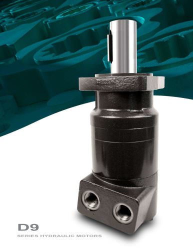
 D9
D914 Pages
 Product Catalog
258 Pages
 FD
FD6 Pages
 BK series 910
4 Pages
 DT
DT20 Pages
 WS
WS22 Pages
 RS D9 Series Hydraulic Motors
16 Pages
 RG Series
32 Pages
 White Hydraulics - Drive products
204 Pages

- Hydraulic motor
- Magnetic speed sensor
- Rotational speed sensor
- Flow divider
- Orbital hydraulic motor
- Non-contact speed sensor
- Gear hydraulic motor
- Hydraulic flow divider
- Industrial hydraulic motor
- Compact speed sensor
- Compact hydraulic motor
- High-pressure hydraulic motor
- Robust speed sensor
- Axle steering system
- Variable-displacement hydraulic motor
- High-torque hydraulic motor
- Hydraulic motor for heavy-duty applications
- Low-speed hydraulic motor
- 2-channel flow divider
- Two-speed hydraulic motor