


OMSW

OMSW
The document provides technical information on OMSW orbital motors with brake nose by WHITE Drive Motors & Steering LLC. It includes essential details on speed, torque, and output for selecting the appropriate motor size for specific applications. Function diagrams are provided for each motor size to assist in this selection process.
This section outlines specifications for various OMSW motor sizes, including geometric displacement, maximum speed, torque, output, pressure drop, and oil flow. Key parameters include:
- Maximum speed ranges from 155 to 600 rpm depending on the motor size.
- Maximum torque varies from 375 to 865 N•m for continuous operation.
- Maximum pressure drop is specified for continuous, intermittent, and peak operations.
Maximum inlet and return pressures are specified for continuous, intermittent, and peak operations. The document also details permissible shaft loads, emphasizing the use of tapered roller bearings to handle high axial and radial forces.
Function diagrams for each motor size (OMS 125, 160, 200, 250, 315, 400, 500) illustrate the continuous and intermittent operational ranges. These diagrams are based on tests conducted with mineral-based hydraulic oil at specific viscosities and temperatures.
The document includes dimensions for OMSW motors with various port and valve configurations, such as side port with check valve and end port with drain connection.
WHITE reserves the right to alter product specifications without notice, and all trademarks mentioned are the property of their respective companies.
The document provides technical specifications and dimensions for various models of OMSW motors, focusing on different configurations such as side port with check valve, side port with drain connection, end port with check valve, and end port with drain connection. It includes detailed measurements and threading information for each model type.
The document outlines the continuous and intermittent operational ranges for OMS 400 and OMS 500 models, emphasizing that the intermittent range should not exceed 10% operation every minute.
Detailed dimensions are provided for each OMSW model (125, 160, 200, 250, 315, 400, 500) across different configurations. Measurements include L1, L2, and L3 dimensions in both millimeters and inches, along with threading details for external brakes and ports.
The document includes several figures and tables illustrating the function diagrams, shaft versions, port thread versions, and specific dimensions for each motor configuration. Key tables include technical data, maximum pressure, and oil flow in the drain line.
WHITE Drive Motors & Steering LLC reserves the right to alter products without notice and disclaims responsibility for errors in printed materials. All trademarks are acknowledged as the property of their respective companies.
Catalog excerpts

Technical Information OMSW with brake nose orbital motors
Open the catalog to page 1
accept no responsibility for possible errors in catalogues, brochures, and other printed material. WHITE reserves the right to alter its products without notice. This also applies to products already on order provided that such alterations can be made subsequent changes being necessary in specifications already agreed. All trademarks in this material are the property of the respective companies. WHITE and the WHITE logotype are trademarks of WHITE Drive Motors & Steering LLC and WHITE Drive Motors and Steering Sp. z o.o.. All rights reserved.
Open the catalog to page 2
Contents Chapter 1 Product overview _______________________________________________________________ 4 Speed, torque and output _________________________________________________________________________ 5 Chapter 2 Technical data _________________________________________________________________ 6 Technical data for OMSW__________________________________________________________________________ 7 Max. pressure ___________________________________________________________________________________________ 8 Max. permissible shaft seal pressure ________________________________________________________________...
Open the catalog to page 3
Chapter 1 General Information Topics: • Speed, torque and output WHITE can accept no responsibility for possible errors in catalogues, brochures, and other printed material. WHITE reserves the right to alter its products without notice. This also applies to products already on order provided that such alterations can be made without subsequent changes being necessary in specifications already agreed. All trademarks in this material are the property of the respective companies. WHITE and the WHITE logotype are trademarks of WHITE Drive Motors & Steering LLC and WHITE Drive Motors and Steering...
Open the catalog to page 4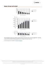
Speed, torque and output Intermittent values Continuous values Intermittent values Continuous values Intermittent values Continuous values The bar diagrams above are useful for a quick selection of relevant motor size for the application. The final motor size can be determined by using the function diagram for each motor size. Function diagrams for OMSW see Function diagrams. WHITE can accept no responsibility for possible errors in catalogues, brochures, and other printed material. WHITE reserves the right to alter its products without notice. This also applies to products already on order provided...
Open the catalog to page 5
Chapter 2 Technical data Topics: • • • • • • • Technical data for OMSW Max. permissible shaft seal pressure Oil flow in drain line Direction of shaft rotation Function diagrams Shaft version Port thread versions WHITE can accept no responsibility for possible errors in catalogues, brochures, and other printed material. WHITE reserves the right to alter its products without notice. This also applies to products already on order provided that such alterations can be made without subsequent changes being necessary in specifications already agreed. All trademarks in this material are the property...
Open the catalog to page 6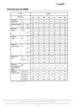
Technical data for OMSW Type Motor size Geometric displacement Maximum speed min [rpm] Maximum torque int. Maximum pressure drop peak 2) Maximum oil flow Maximum starting pressure with unloaded shaft Minimum starting torque l/min cont. [US gal/min] int.1) bar [psi] at maximum press drop cont. N•m [lbf•in] at maximum press drop int.1) N•m [lbf•in] Table 1 Technical data for OMSW WHITE can accept no responsibility for possible errors in catalogues, brochures, and other printed material. WHITE reserves the right to alter its products without notice. This also applies to products already on order...
Open the catalog to page 7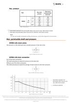
Max. pressure Max inlet pressure cont. OMSW Max return pressure with drain line Intermittent operation: the permissible values may occur for max. 10% of every minute. Peak load: the permissible values may occur for maximum 1% of every minute. Note: For max. permissible combination of flow and pressure, see function diagram for actual motor. Max. permissible shaft seal pressure OMSW with check valves The pressure on the shaft seal never exceeds pressure in the return line Figure 4 OMSW with check valves OMSW with drain connection Use of the drain connection: The shaft seal pressure equals the...
Open the catalog to page 8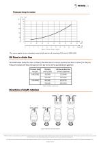
Pressure drop in motor Figure 7 Pressure Drop in OMSW The curve applies to an unloaded motor shaft and an oil viscosity of 35 mm2/s [165 SUS] Oil flow in drain line The table below shows the max. oil flow in the drain line at a return pressure less than 5-10 bar [75-150 psi]. Pressure Viscosity Oil flow in drop drain line bar mm2/s l/min [psi] [SUS] [US gal/min] Pressure drop bar [psi] Oil flow in drain line l/min [US gal/min] Table 3 Oil flow in drain line Direction of shaft rotation Figure 8 direction of shaft rotation WHITE can accept no responsibility for possible errors in catalogues, brochures,...
Open the catalog to page 9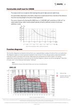
Permissible shaft load for OMSW The output shaft runs in tapered roller bearings that permit high axial and radial forces. The permissible radial load on the shaft is shown for an axial load of 0 N as a function of the distance from the mounting flange to the point of load application. The curve is based on B10 Bearing life (2000 hours or 12 000 000 shaft revolutions at 100 min-1) at rated output torque, when mineral-based hydraulic oil with a sufficient content of anti-wear additives, is used. Figure 9 Mounting flange: Wheel / Shaft: All shaft types Function diagrams The function diagrams are...
Open the catalog to page 10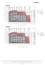
Continuous range Intermittent range (max. 10% operation every minute) Figure 11 Function diagram OMS 160 Continuous range Intermittent range (max. 10% operation every minute) Figure 12 Function diagram OMS 200 WHITE can accept no responsibility for possible errors in catalogues, brochures, and other printed material. WHITE reserves the right to alter its products without notice. This also applies to products already on order provided that such alterations can be made without subsequent changes being necessary in specifications already agreed. All trademarks in this material are the property of...
Open the catalog to page 11All White Drive Motors And Steering catalogs and technical brochures
 White Brochure
20 Pages
 OML | OMM Technical Information
32 Pages
 ORBITAL X Technical Information
54 Pages
 OMS Technical Information
53 Pages
 OMSU Technical Information
17 Pages
 OMEW Technical Information
19 Pages
 RE Technical Information
59 Pages
 HP 30 Technical Information
42 Pages
 RS Technical Information
36 Pages
 WS Technical Information
36 Pages
 DH | DS Technical Information
43 Pages
 SbX Technical Information
28 Pages
 OSPM Technical Information
33 Pages
 LAGC Technical-Information
20 Pages
 LAGU Technical-Information
18 Pages
 LAGZ Technical Information
22 Pages
 S10 | S20 Technical Information
39 Pages
Archived catalogs
 OMS
OMS53 Pages
 VIS 40, 45
65 Pages
 HP 30
HP 3042 Pages
 RS Orbital Motors
36 Pages
 WM
WM8 Pages
 WD
WD14 Pages
 WP
WP18 Pages
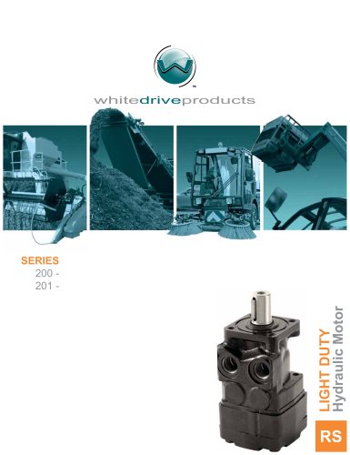 RS Series 200-201
15 Pages
 WR
WR18 Pages
 WG
WG22 Pages
 HB/HK
HB/HK22 Pages
 WS
WS26 Pages
 CE
CE21 Pages
 RE
RE27 Pages
 DR
DR23 Pages
 DT
DT18 Pages
 BK series 913
4 Pages
 SB
SB7 Pages
 FD
FD6 Pages
 2012 Product Catalog
259 Pages
 HB
HB20 Pages
 D9
D914 Pages
 Product Catalog
258 Pages
 FD
FD6 Pages
 BK series 910
4 Pages
 DT
DT20 Pages
 WS
WS22 Pages
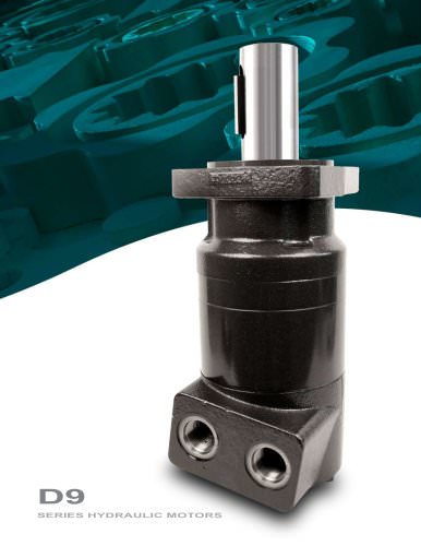 RS D9 Series Hydraulic Motors
16 Pages
 RG Series
32 Pages
 White Hydraulics - Drive products
204 Pages

- Hydraulic motor
- Magnetic speed sensor
- Rotational speed sensor
- Orbital hydraulic motor
- Flow divider
- Gear hydraulic motor
- Non-contact speed sensor
- Industrial hydraulic motor
- Hydraulic flow divider
- Compact speed sensor
- Compact hydraulic motor
- High-pressure hydraulic motor
- Axle steering system
- Robust speed sensor
- High-torque hydraulic motor
- Variable-displacement hydraulic motor
- Hydraulic motor for heavy-duty applications
- Low-speed hydraulic motor
- 2-channel flow divider
- Two-speed hydraulic motor