- Catalogs
- White Drive Motors And Steering
- OMSU Technical Information
OMSU Technical Information
1 /17Pages
OMSU Technical Information
1 /17Pages
Catalog excerpts

MOTORS Technical Information OMSU Series 3 Orbital Motor
Open the catalog to page 1
White is a leading global provider of motor and steering solutions that power the evolution of mobile and industrial applications around the world.
Open the catalog to page 2
WHITE can accept no responsibility for possible errors in catalogues, brochures, and other printed material. WHITE reserves the right to alter its products without notice. This also applies to products already on order provided that such alterations can be made without subsequent changes being necessary in specifications already agreed. All trademarks in this material are the property of the respective companies. WHITE and the WHITE logotype are trademarks of WHITE Drive Motors & Steering LLC and WHITE Drive Motors and Steering Sp. z o.o.. All rights reserved.
Open the catalog to page 3
Chapter 1 Technical Data Topics: • • Technical data Check valves WHITE can accept no responsibility for possible errors in catalogues, brochures, and other printed material. WHITE reserves the right to alter its products without notice. This also applies to products already on order provided that such alterations can be made without subsequent changes being necessary in specifications already agreed. All trademarks in this material are the property of the respective companies. WHITE and the WHITE logotype are trademarks of WHITE Drive Motors & Steering LLC and WHITE Drive Motors and Steering...
Open the catalog to page 4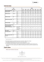
Table 1 Technical data (1) Intermittent operation: permissible values may occur for max. 10% of every minute. (2) Peak load: permissible values may occur for max. 1% of every minute. (3) At speeds lower than those given, the motor cannot be expected to run evenly. (4) If no drain line is fitted, the built-in check valves ensure that the case pressure is equal to the pressure in the return line. The max. case pressure for OMSU is dictated by the technical data of the component to be attached. OMSU motors have built-in check valves. WHITE can accept no responsibility for possible errors in catalogues,...
Open the catalog to page 5
Chapter 2 Dimensions Topics: • OMSU dimensions WHITE can accept no responsibility for possible errors in catalogues, brochures, and other printed material. WHITE reserves the right to alter its products without notice. This also applies to products already on order provided that such alterations can be made without subsequent changes being necessary in specifications already agreed. All trademarks in this material are the property of the respective companies. WHITE and the WHITE logotype are trademarks of WHITE Drive Motors & Steering LLC and WHITE Drive Motors and Steering Sp. z o.o.. All rights...
Open the catalog to page 6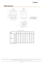
C: Drain hole 05 +0.2 -0.1 D: M10; 11 mm deep E: G 1/2; 15 mm deepFigure 2 OMSU dimensions Type Table 2 OMSU dimensions WHITE can accept no responsibility for possible errors in catalogues, brochures, and other printed material. WHITE reserves the right to alter its products without notice. This also applies to products already on order provided that such alterations can be made without subsequent changes being necessary in specifications already agreed. All trademarks in this material are the property of the respective companies. WHITE and the WHITE logotype are trademarks of WHITE Drive Motors...
Open the catalog to page 7
Chapter 3 General dataTopics: • Connection dimensions, attached component • Internal spline data for the component to be attached • Drain connection on OMSU or attached component • Installing OMSU • Maximum tightening torque • Checking OMSU • Exploded view OMSU • OMSU spare parts list WHITE can accept no responsibility for possible errors in catalogues, brochures, and other printed material. WHITE reserves the right to alter its products without notice. This also applies to products already on order provided that such alterations can be made without subsequent changes being necessary in specifications...
Open the catalog to page 8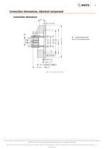
Connection dimensions, attached component Connection dimensions Hardened stop plate B or C: Oil circulation holes Figure 3 Connection dimensions WHITE can accept no responsibility for possible errors in catalogues, brochures, and other printed material. WHITE reserves the right to alter its products without notice. This also applies to products already on order provided that such alterations can be made without subsequent changes being necessary in specifications already agreed. All trademarks in this material are the property of the respective companies. WHITE and the WHITE logotype are trademarks...
Open the catalog to page 9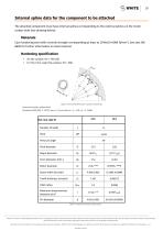
10 Internal spline data for the component to be attached The attached component must have internal splines corresponding to the external splines on the motor cardan shaft (see drawing below). Case hardening steel with a tensile strength corresponding at least to 20 MoCr4 (900 N/mm2). See also SAE 8620 for further information on steel material. Internal involute spline data Standard ANS B92. 1-1970, class 5 (corrected m • x = 0.8; m = 2.1166) Table 3 Internal involute spline data WHITE can accept no responsibility for possible errors in catalogues, brochures, and other printed material. WHITE...
Open the catalog to page 10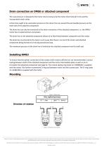
Drain connection on OMSU or attached component The case pressure is released to the motor return pressure by the motor drain hole (0 5 mm) and the incorporated check valves. A drain line ought to be used when pressure in the return line can exceed the permissible pressure on the shaft seal of the attached component. The drain line can only be connected to the drain connection of the attached component, i.e. the OMSU motor has no external drain connection. The drain line on the attached component allows oil to flow freely between component and the motor. The drain line must be led to the tank...
Open the catalog to page 11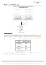
Maximum tightening torque Maximum tightening torque Table 4 Maximum tightening torque In order to make sure that the OMSU counterpart is correct, the drain flow should be measured on the first of each new application. Any subsequent modification of the counterpart should imply new checking. When the motor is fitted onto the counter part with the correct tightening torque, the drain flow is measured at Q = 30 I/min and an oil viscosity of 35 mm2/s at differential pressure: Table 5 Differential pressure After a minimum of 5 min. of operation the drain flow shall be minimum 0.03 l/min and maximum...
Open the catalog to page 12All White Drive Motors And Steering catalogs and technical brochures
 White Brochure
20 Pages
 OML | OMM Technical Information
32 Pages
 ORBITAL X Technical Information
54 Pages
 OMS Technical Information
53 Pages
 OMEW Technical Information
19 Pages
 RE Technical Information
59 Pages
 HP 30 Technical Information
42 Pages
 RS Technical Information
36 Pages
 WS Technical Information
36 Pages
 DH | DS Technical Information
43 Pages
 SbX Technical Information
28 Pages
 OSPM Technical Information
33 Pages
 LAGC Technical-Information
20 Pages
 LAGU Technical-Information
18 Pages
 LAGZ Technical Information
22 Pages
 S10 | S20 Technical Information
39 Pages

Archived catalogs
 OMS
OMS53 Pages
 OMSW
OMSW21 Pages
 VIS 40, 45
65 Pages
 HP 30
HP 3042 Pages
 RS Orbital Motors
36 Pages
 WM
WM8 Pages
 WD
WD14 Pages
 WP
WP18 Pages
 RS Series 200-201
15 Pages
 WR
WR18 Pages
 WG
WG22 Pages
 HB/HK
HB/HK22 Pages
 WS
WS26 Pages
 CE
CE21 Pages
 RE
RE27 Pages
 DR
DR23 Pages
 DT
DT18 Pages
 BK series 913
4 Pages
 SB
SB7 Pages
 FD
FD6 Pages
 2012 Product Catalog
259 Pages
 HB
HB20 Pages
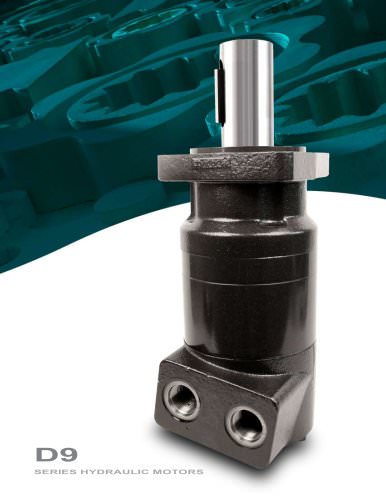
 D9
D914 Pages
 Product Catalog
258 Pages
 FD
FD6 Pages
 BK series 910
4 Pages
 DT
DT20 Pages
 WS
WS22 Pages
 RS D9 Series Hydraulic Motors
16 Pages
 RG Series
32 Pages
 White Hydraulics - Drive products
204 Pages

- Hydraulic motor
- Magnetic speed sensor
- Rotational speed sensor
- Flow divider
- Orbital hydraulic motor
- Non-contact speed sensor
- Gear hydraulic motor
- Hydraulic flow divider
- Industrial hydraulic motor
- Compact speed sensor
- Compact hydraulic motor
- High-pressure hydraulic motor
- Robust speed sensor
- Axle steering system
- Variable-displacement hydraulic motor
- High-torque hydraulic motor
- Hydraulic motor for heavy-duty applications
- Low-speed hydraulic motor
- 2-channel flow divider
- Two-speed hydraulic motor