- Catalogs
- White Drive Motors And Steering
- LAGU Technical-Information
LAGU Technical-Information
1 /18Pages
LAGU Technical-Information
1 /18Pages
Catalog excerpts

Technical Information Steering Unit LAGU /'/, WHITE together in motion
Open the catalog to page 1
White is a leading global provider of motor and steering solutions that power the evolution of mobile and industrial applications around the world.
Open the catalog to page 2
Contents: Chapter 1 _______________________________________________________________________ 4 Steering Unit LAGU Technical Information _________________________________________________ 4 Features _____________________________________________________________________________________ 6 Ordering details _______________________________________________________________________________ 6 Function, section ______________________________________________________________________________ 8 Versions _____________________________________________________________________________________ 9 Functions in a steering...
Open the catalog to page 3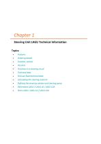
• Ordering details • Function, section • Functions in a steering circuit • Technical data • Pressure fluid technical data • Calculating the steering moment • Defining the steering cylinder and steering pump • Dimensions LAGU/ LAGU LD / LAGU LDA • Ports LAGU/ LAGU LD / LAGU LDA
Open the catalog to page 4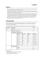
• The LAGU steering unit is used in hydraulic steering circuits on vehicles and mobile machines that have high axle loads and maximum travel speeds of 60 kph. • With the aid of a steering unit even heavy vehicles can be easily steered. The absence of a mechanical connection between the steering unit and steering axle allows the designer to realize solutions which would be impossible with conventional steering systems. • If the oil supply to the steering unit fails, vehicles can easily be steered manually with the help of the LAGU. The LAGU acts also as a hand pump but the driving torque from...
Open the catalog to page 5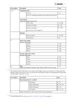
6 For thread dimensions see Dimensions LAGU/LAGULD /LAGULDA on page 18
Open the catalog to page 6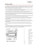
Function, section Control spool (1) of the control valve is rotated via the steering column in relation to control sleeve (2). This opens cross-sections between the spool and the sleeve. The pressurized oil acts on the rotor set (3) and sets the latter into motion. The oil is then fed via the rotor set to the steering cylinder. The rotation of the rotor acts on the sleeve, which then follows the rotary movement of the spool. The size of the opened cross-section depends on the turning speed of the steering wheel and on the steering pressure, on Load-Sensing versions it depends exclusively on the...
Open the catalog to page 7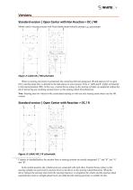
Versions Standard version | Open Center with Non Reaction = OC / NR Mainly used in steering systems with fixed displacement hydraulic pumps (e.g. gear pumps). Figure 2: LAGU OC / NR schematic When no steering movement is performed, the connection between pump port (P) and tank port (T) is open (OC), and the pump flow is directed to the tank almost at zero pressure. Ports L 1 (left) and R1 (right) are blocked in the neutral position (NR). In this way, external forces acting via the steering cylinder are supported without the driver perceiving any resulting reaction forces on the steering wheel...
Open the catalog to page 8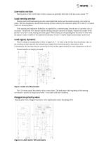
Low-noise version Steering units of the LAGU Open Center versions are generally delivered in the low-noise variant “N“. Load sensing version Steering units with load sensing provide a load signal that can be used to control a priority valve and/or a pump. They are designed as closed center steering systems whereby the connection pump (P) to tank (T) is locked while in a neutral position. If the steering and implement hydraulics are supplied by a common pump, then the use of a priority valve is necessary. The priority valve ensures that the steering unit gets a priority oil supply, whereby the...
Open the catalog to page 9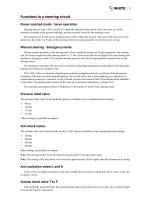
11 Functions in a steering circuitPower-assisted mode - Servo operation Steering units of type LAGU consist of a manually operated rotary spool valve, one rotor set, which operates according to the gerotor principle, and the required valves for the steering circuit. The nominal size for the power-assisted mode results of the rotor set size. The size of the rotor set is to be selected so that with 3 to 5 turns of the steering wheel it becomes possible to steer from lock to lock. During normal operation of the steering unit, when a sufficient amount of oil gets supplied to the steering unit, the...
Open the catalog to page 10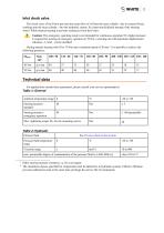
'5, WHITEInlet check valve The check valve of the P-port prevents the return flow of oil from the steer cylinder - due to external forces working onto the steer cylinder - into the hydraulic system. So it prevents kickback turning of the steering wheel. While manual steering it prevents sucking air from the P-port. I . Caution: The emergency operating mode is not intended for continuous operation! If a higher pressure is required for steering in emergency operation at 70 Nm, a steering unit with automatic displacement reduction - LAGZ - can be installed. During manual steering with 50 or 70 Nm...
Open the catalog to page 11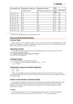
'5, WHITE Steering unit Type 3 Related to the steering speed of 100 steering rotations/min. Before carrying out any engineering please refer to the extensive information regarding pressure fluid selection and application conditions in standards or manufacturer instructions. For pressure fluids that require FKM or other seals please contact your sales contact. We recommend that the operating viscosity (at operating temperature) for efficiency and service life, is selected within the optimum range of v opt = optimum operating viscosity range 16 to 46 mm2/s with reference to the temperature. For...
Open the catalog to page 12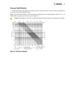
Pressure fluid filtration The finer the filtration the higher the cleanliness class of the pressure fluid is achieved and so the higher the service life of the entire hydraulic system. Note: To ensure the functionality of the steering pump a minimum pressure fluid cleanliness class of 19 / 16 / 13 to ISO 4406 is necessary (see Technical data on page 12). Caution: Operating the unit with contaminated hydraulic fluid may lead to the steering system failing. Figure 6: Selection diagram
Open the catalog to page 13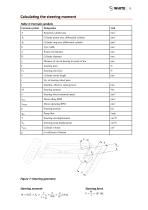
Calculating the steering moment Table 3: Formula symbols Formula symbol Required cylinder area Cylinder piston area, differential cylinder Cylinder ring area, differential cylinder Tyre width Cylinder diameter Distance of swivel bearing to center of tire Steering force Steering axle force Cylinder stroke length No. of steering wheel turns Smallest, effective steering lever Steering moment Steering wheel rotational speed Steering pressure Pump flow Steering unit displacement Steering pump displacement Cylinder volume Figure 7: Steering geometry Steering moment ݑ = 0,05 װݐٰݐ ԃ
Open the catalog to page 14All White Drive Motors And Steering catalogs and technical brochures
 White Brochure
20 Pages
 OML | OMM Technical Information
32 Pages
 ORBITAL X Technical Information
54 Pages
 OMS Technical Information
53 Pages
 OMSU Technical Information
17 Pages
 OMEW Technical Information
19 Pages
 RE Technical Information
59 Pages
 HP 30 Technical Information
42 Pages
 RS Technical Information
36 Pages
 WS Technical Information
36 Pages
 DH | DS Technical Information
43 Pages
 SbX Technical Information
28 Pages
 OSPM Technical Information
33 Pages
 LAGC Technical-Information
20 Pages
 LAGZ Technical Information
22 Pages
 S10 | S20 Technical Information
39 Pages
Archived catalogs
 OMS
OMS53 Pages
 OMSW
OMSW21 Pages
 VIS 40, 45
65 Pages
 HP 30
HP 3042 Pages
 RS Orbital Motors
36 Pages
 WM
WM8 Pages
 WD
WD14 Pages
 WP
WP18 Pages
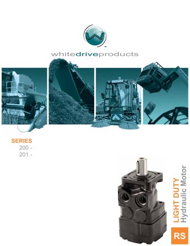 RS Series 200-201
15 Pages
 WR
WR18 Pages
 WG
WG22 Pages
 HB/HK
HB/HK22 Pages
 WS
WS26 Pages
 CE
CE21 Pages
 RE
RE27 Pages
 DR
DR23 Pages
 DT
DT18 Pages
 BK series 913
4 Pages
 SB
SB7 Pages
 FD
FD6 Pages
 2012 Product Catalog
259 Pages
 HB
HB20 Pages
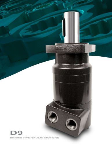
 D9
D914 Pages
 Product Catalog
258 Pages
 FD
FD6 Pages
 BK series 910
4 Pages
 DT
DT20 Pages
 WS
WS22 Pages
 RS D9 Series Hydraulic Motors
16 Pages
 RG Series
32 Pages
 White Hydraulics - Drive products
204 Pages

- Hydraulic motor
- Magnetic speed sensor
- Rotational speed sensor
- Flow divider
- Orbital hydraulic motor
- Non-contact speed sensor
- Gear hydraulic motor
- Hydraulic flow divider
- Industrial hydraulic motor
- Compact speed sensor
- Compact hydraulic motor
- High-pressure hydraulic motor
- Robust speed sensor
- Axle steering system
- Variable-displacement hydraulic motor
- High-torque hydraulic motor
- Hydraulic motor for heavy-duty applications
- Low-speed hydraulic motor
- 2-channel flow divider
- Two-speed hydraulic motor