
- Catalogs
- White Drive Motors And Steering
- EMS Speed Sensor Technical Information


EMS Speed Sensor Technical Information
EMS Speed Sensor Technical Information
The document provides a detailed overview of the EMD Speed Sensor designed for Orbital Motors. It emphasizes the sensor's capability to detect shaft speed and direction using a rotating magnetic field from a magnet attached to the motor's shaft. The sensor is ideal for rugged outdoor, mobile, or heavy industrial applications and does not require calibration.
The sensor features high resolution, easy mounting, and robustness due to its non-contact design with oil. It supports Pulse, Quadrature, and CAN modes, with a speed range up to 2500 rpm. It includes a DEUTSCH DT connector and is compact and adaptable.
The sensor operates within a supply voltage of 9 - 36 Vdc and withstands temperatures from -30°C to 60°C. It is rated IP 69K for enclosure protection and can endure vibrations up to 30 G and shocks up to 50 G.
Various part numbers are available based on the required output mode and compatibility with different motor models. Detailed ordering information is provided for each configuration.
Instructions for mounting the sensor and wiring diagrams for different modes are included. The sensor can be mounted in 36 different positions and is designed for easy installation.
Drawings for different motor models (OMM, OMP/OMR, OMS) with the EMD Speed Sensor are included, showing sensor integration with the motors.
The document includes warnings about potential sensor failures and stresses the need for hazard and risk assessments in applications. It notes that the sensor requires 1-2 revolutions after power-up to generate an output signal.
This document provides technical specifications, procedures, and guidelines for the OMS EMD speed sensor used in WHITE Drive Motors & Steering products. It includes information on filter parameters, positioning applications, and installation instructions.
The document outlines the dimensions and configurations of the OMS EMD speed sensor, noting that motor length varies with displacement. It emphasizes that WHITE reserves the right to alter product specifications without notice.
The document discusses the use of a Moving Average Pulse period time Number (MAPN) to reduce noise in frequency calculations. The MAPN can be set to specific values (1, 2, 4, 8, 16, 32, 64) and can be dynamic, adjusting based on detected speed using Dynamic 1 or Dynamic 2 filter calculations.
The EMD sensor can be used as an encoder in positioning applications, with recommendations to use pulse mode 180 PPR or Quadrature mode to avoid errors. The document provides typical backlash values for different Orbit motors.
Instructions are provided for mounting the EMD speed sensor on LSHT motors, including positioning and securing the sensor. A warning is included about potential sensor failures and the importance of conducting hazard and risk assessments.
The document includes various figures and tables detailing sensor principles, dimensions, pin locations, and specifications, as well as MAPN values and typical motor backlash.
WHITE disclaims responsibility for errors in printed materials and reserves the right to make product changes without notice. All trademarks are acknowledged as the property of their respective companies.
Catalog excerpts
MOTORS USER MANUAL Orbital Motor, EMD Speed Sensor
Open the catalog to page 1
White is a leading global provider of motor and steering solutions that power the evolution of mobile and industrial applications around the world.
Open the catalog to page 2
Contents Chapter 1 Product overview ______________________________________________________________ 4 Description _____________________________________________________________________________________ 5 EMD Speed Sensor for Orbital Motors _______________________________________________________________ 6 EMD Speed Sensor features _______________________________________________________________________ 6 EMD Speed Sensor dimensions _____________________________________________________________________ 6 EMD Speed Sensor pinout _________________________________________________________________________...
Open the catalog to page 3
• EMD Speed Sensor for Orbital Motors • EMD Speed Sensor features • EMD Speed Sensor dimensions • EMD Speed Sensor pinout • EMD Speed Sensor mating connector • EMD Speed Sensor specifications • EMD speed sensor ordering information • Pulse mode • Quadrature mode Please note that the EMD speed sensor may fail. Output signals may not represent correct rotation speed or direction. Any application of the EMD speed sensor should be subjected to appropriate hazard and risk assessment, according to relevant safety standards for the application. Reliability data MTBF for the EMD speed sensor are available...
Open the catalog to page 4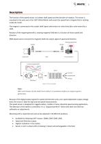
Description The function of the speed sensor is to detect shaft speed and the direction of rotation. The sensor is mounted to the end cover of an LSHT Orbital Motor and senses the speed from a magnet that is rotating inside the motor. The magnet is connected to the cardan shaft (spool valve motor) or valve drive (disc valve motor) by a shaft. Rotation of the magnet generates a rotating magnetic field that is a function of motor speed and direction. EMD-Speed sensor converts this magnetic field into output signal of speed and direction. Figure 1 Sensor principle Note: After each Power-Up the shaft...
Open the catalog to page 5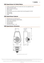
• Flexible and adaptable speed sensor solution that covers many application needs • Speed and Direction output • Highest resolution in the market • Easy mounting • Sensor is not in contact with oil making it robust and exchangeable in the field • Compact design • Patented Design • EMD speed sensor up to 180 pulses/rev • Rotation speed and direction output available • Push-pull amplifier WHITE can accept no responsibility for possible errors in catalogues, brochures, and other printed material. WHITE reserves the right to alter its products without notice. This also applies to products already...
Open the catalog to page 6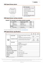
EMD Speed Sensor pinout Figure 3 Pin location Table 1 Pinout description EMD Speed Sensor mating connector Deutsch® DT connector 6 pin mating connector assembly Table 3 Speed sensor specifications WHITE can accept no responsibility for possible errors in catalogues, brochures, and other printed material. WHITE reserves the right to alter its products without notice. This also applies to products already on order provided that such alterations can be made without subsequent changes being necessary in specifications already agreed. All trademarks in this material are the property of the respective...
Open the catalog to page 7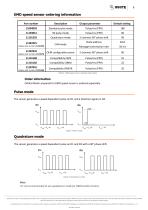
Table 4 EMD speed sensor ordering information Order information Orbital Motor prepared for EMD speed sensor is ordered separately. The sensor generates a speed dependent pulse on D1 and a direction signal on D2. The sensor generates a speed dependent pulse on D1 and D2 with a 90° phase shift. It's not recommended to use quadrature mode for OMM orbital motors. WHITE can accept no responsibility for possible errors in catalogues, brochures, and other printed material. WHITE reserves the right to alter its products without notice. This also applies to products already on order provided that such...
Open the catalog to page 8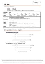
CAN mode Cyclic message specification Interface: Baud rate: Transmit rate: 10, 20, 50 (default), 100 or 200 ms (cyclic message transmission) Wiring diagram: Pulse and quadrature mode WHITE can accept no responsibility for possible errors in catalogues, brochures, and other printed material. WHITE reserves the right to alter its products without notice. This also applies to products already on order provided that such alterations can be made without subsequent changes being necessary in specifications already agreed. All trademarks in this material are the property of the respective companies....
Open the catalog to page 9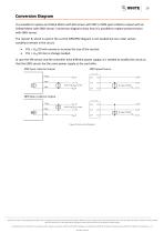
Conversion Diagram It is possible to replace an Orbital Motor with EM-sensor with PNP or NPN open collector output with an Orbital Motor with EMD-sensor. Conversion diagrams show how it is possible to replace present sensor with EMD-sensor. The resistor Rl which is used in the current NPN/PNP diagram is not needed but can under certain conditions remain in the circuit: • If Rl < Udc/10 mA remove or increase the size of the resistor. In case the EM-sensor and the controller have different power supply, it is needed to modify the circuit so that the EMD-sensor has the same power supply as the controller....
Open the catalog to page 10
11 Chapter 2 Sectional drawingsTopics: • OMM EMD WHITE can accept no responsibility for possible errors in catalogues, brochures, and other printed material. WHITE reserves the right to alter its products without notice. This also applies to products already on order provided that such alterations can be made without subsequent changes being necessary in specifications already agreed. All trademarks in this material are the property of the respective companies. WHITE and the WHITE logotype are trademarks of WHITE Drive Motors & Steering LLC and WHITE Drive Motors and Steering sp. z o.o..
Open the catalog to page 11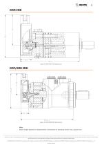
Figure 9 OMM EMD with Speed Sensor Figure 10 OMP/OMR EMD Speed Sensor Note: Motor length depends on displacement. Dimensions on drawings are for max. gearset size. WHITE can accept no responsibility for possible errors in catalogues, brochures, and other printed material. WHITE reserves the right to alter its products without notice. This also applies to products already on order provided that such alterations can be made without subsequent changes being necessary in specifications already agreed. All trademarks in this material are the property of the respective companies. WHITE and the WHITE...
Open the catalog to page 12All White Drive Motors And Steering catalogs and technical brochures
 White Brochure
20 Pages
 OML | OMM Technical Information
32 Pages
 ORBITAL X Technical Information
54 Pages
 OMS Technical Information
53 Pages
 OMSU Technical Information
17 Pages
 OMEW Technical Information
19 Pages
 RE Technical Information
59 Pages
 HP 30 Technical Information
42 Pages
 RS Technical Information
36 Pages
 WS Technical Information
36 Pages
 DH | DS Technical Information
43 Pages
 SbX Technical Information
28 Pages
 OSPM Technical Information
33 Pages
 LAGC Technical-Information
20 Pages
 LAGU Technical-Information
18 Pages
 LAGZ Technical Information
22 Pages
 S10 | S20 Technical Information
39 Pages

Archived catalogs
 OMS
OMS53 Pages
 OMSW
OMSW21 Pages
 VIS 40, 45
65 Pages
 HP 30
HP 3042 Pages
 RS Orbital Motors
36 Pages
 WM
WM8 Pages
 WD
WD14 Pages
 WP
WP18 Pages
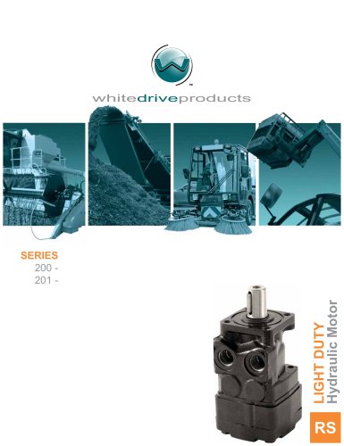 RS Series 200-201
15 Pages
 WR
WR18 Pages
 WG
WG22 Pages
 HB/HK
HB/HK22 Pages
 WS
WS26 Pages
 CE
CE21 Pages
 RE
RE27 Pages
 DR
DR23 Pages
 DT
DT18 Pages
 BK series 913
4 Pages
 SB
SB7 Pages
 FD
FD6 Pages
 2012 Product Catalog
259 Pages
 HB
HB20 Pages
 D9
D914 Pages
 Product Catalog
258 Pages
 FD
FD6 Pages
 BK series 910
4 Pages
 DT
DT20 Pages
 WS
WS22 Pages
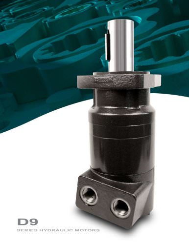 RS D9 Series Hydraulic Motors
16 Pages
 RG Series
32 Pages
 White Hydraulics - Drive products
204 Pages

- Hydraulic motor
- Magnetic speed sensor
- Rotational speed sensor
- Orbital hydraulic motor
- Flow divider
- Gear hydraulic motor
- Non-contact speed sensor
- Industrial hydraulic motor
- Hydraulic flow divider
- Compact speed sensor
- Compact hydraulic motor
- High-pressure hydraulic motor
- Axle steering system
- Robust speed sensor
- High-torque hydraulic motor
- Variable-displacement hydraulic motor
- Hydraulic motor for heavy-duty applications
- Low-speed hydraulic motor
- 2-channel flow divider
- Two-speed hydraulic motor