DR
1 /23Pages

DR
1 /23Pages
Catalog excerpts

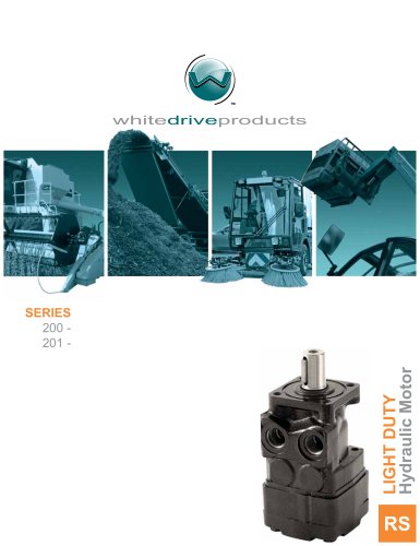
SERIES 600 610 620 630 640 - MEDIUM DUTY Hydraulic Motor & Brake whitedriveproducts DR
Open the catalog to page 1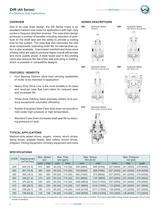
For Medium Duty Applications white drive pro ducts Due to its case drain design, the DR Series motor is an excellent medium size motor for applications with high-duty cycles or frequent direction reversal. The case drain design produces a number of benefits including reduction of pres- sure on the shaft seal and the ability to provide a cooling loop for the system. The case flow also lubricates the vital drive components, extending motor life. An internal drain op- tion is also available. A laminated manifold and three-zone orbiting valve are used to produce higher overall efficiencies and more...
Open the catalog to page 2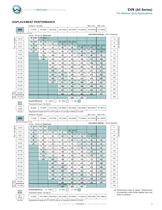
For Medium Duty Applications DISPLACEMENT PERFORMANCE Torque - Nm [Ib-in], Speed rpm Intermittent Ratings -10% of Operation Theoretical Torque - Nm [Ib-in] Displacement tested at 54DC [129DF] with an oil viscosity of 46cSt [213 SUS] Torque - Nm [Ib-in], Speed rpm Intermittent Ratings -10% of Operation Theoretical Torque - Nm [Ib-in] ► Performance data is typical. Performance of production units varies slightly from one Displacement tested at 54°C [129°F] with an oil viscosity of 46cSt [213 SUS] DELIVERING THE POWER TO GET WORK DONE
Open the catalog to page 3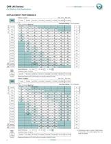
For Medium Duty Applications DISPLACEMENT PERFORMANCE Torque - Nm [Ib-in], Speed rpm Intermittent Ratings -10% of Operation Theoretical Torque - Nm [Ib-in] Displacement tested at 54DC [129DF] with an oil viscosity of 46cSt [213 SUS] Pressure - bars^p^i] Torque - Nm [Ib-in], Speed rpm Intermittent Ratings -10% of Operation Theoretical Torque - Nm [Ib-in] ► Performance data is typical. Performance of production units varies slightly from one Displacement tested at 54°C [129°F] with an oil viscosity of 46cSt [213 SUS] DELIVERING THE POWER TO GET WORK DONE
Open the catalog to page 4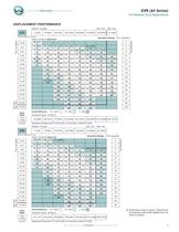
For Medium Duty Applications DISPLACEMENT PERFORMANCE Torque - Nm [Ib-in], Speed rpm Intermittent Ratings -10% of Operation Theoretical Torque - Nm [Ib-in] Displacement tested at 54DC [129DF] with an oil viscosity of 46cSt [213 SUS] Torque - Nm [Ib-in], Speed rpm Intermittent Ratings -10% of Operation Theoretical Torque - Nm [Ib-in] Displacement tested at 54°C [129°F] with an oil viscosity of 46cSt [213 SUS] DELIVERING THE POWER TO GET WORK DONE ► Performance data is typical. Performance of production units varies slightly from one
Open the catalog to page 5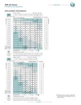
For Medium Duty Applications DISPLACEMENT PERFORMANCE Torque - Nm [Ib-in], Speed rpm Intermittent Ratings -10% of Operation Theoretical Torque - Nm [Ib-in] Displacement tested at 54DC [129DF] with an oil viscosity of 46cSt [213 SUS] Pressure - bar [psi] Max. Cont. Max. Inter. Torque - Nm [Ib-in], Speed rpm Intermittent Ratings -10% of Operation Theoretical Torque - Nm [Ib-in] ► Performance data is typical. Performance of production units varies slightly from one Displacement tested at 54°C [129°F] with an oil viscosity of 46cSt [213 SUS] DELIVERING THE POWER TO GET WORK DONE
Open the catalog to page 6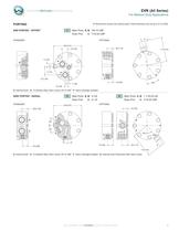
DR (All Series) whitedriveproducts For Medium Duty Applications porting Dimensions shown are without paint. Paint thickness can be up to 0.13 [.005]. END PORTED - OFFSET 1 Main Ports A, B: 7/8-14 UNF Drain Port C: 7/16-20 UNF STANDARD 12° OPTIONAL 126 [4.97] 28 [1.10] 23 [.90] 112 [4.42] F E 11 [.44] B B C 3 [.13] A D A D 37 [1.46] 23 [.90] 7 [.26] 38.5° 10 [.39] D: Internal Drain E: 10 Series/2-Way Valve Cavity 7/8-14 UNF F: Valve Cartridge Installed SIDE PORTED - RADIAL 2 STANDARD Main Ports A, B: G 3/4 Drain Port C: G 1/4 126 [4.97] 5 Main Ports A, B: 1 1/16-20 UN Drain Port C: 7/16-20 UNF...
Open the catalog to page 7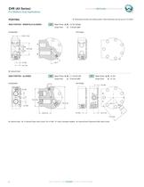
DR (All Series) whitedriveproducts For Medium Duty Applications Porting Dimensions shown are without paint. Paint thickness can be up to 0.13 [.005]. 3 SIDE PORTED - MANIFOLD ALIGNED Main Ports A, B: 11/16” Drilled Drain Port C: 7/16-20 UNF STANDARD OPTIONAL 28.6 [1.125] A A 23 [.90] 64 [2.50] B 23 [.90] B D C D C 23 [.90] 38.5° 30 [1.20] D: Internal Drain SIDE PORTED - ALIGNED 6 STANDARD Main Ports A, B: 1 1/16-20 UN Drain Port C: 7/16-20 UNF 7 Main Ports A, B: G 3/4 Drain Port C: G 1/4 OPTIONAL 13° 23 [.90] C C 23 [.90] A B G A G 116 [4.55] B B 130 [5.10] 23 [.90] 69 [2.73] E A 38.5° D 23 [.90]...
Open the catalog to page 8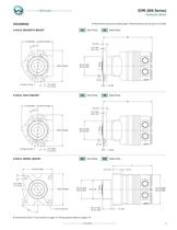
white drive pro ducts Hydraulic Motor ► Dimensions shown are without paint. Paint thickness can be up to 0.13 [.005]. A2 End Ports A8 Side Ports A4 End Ports A9 Side Ports W2 End Ports W8 Side Ports ► Dimensions SS & TT are charted on page 10. Porting options listed on pages 7-8. DELIVERING THE POWER TO GET WORK DONE
Open the catalog to page 9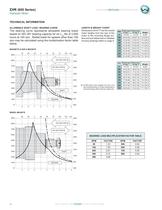
Hydraulic Motor TECHNICAL INFORMATION ALLOWABLE SHAFT LOAD / BEARING CURVE The bearing curve represents allowable bearing loads based on ISO 281 bearing capacity for an L10 life of 2,000 hours at 100 rpm. Radial loads for speeds other than 100 rpm may be calculated using the multiplication factor table LENGTH & WEIGHT CHART Dimensions SS & TTare the overall motor lengths from the rear of the motor to the mounting flange sur- face and are referenced on detailed housing drawings listed on page 9. ► All DR series motor weights can vary ± 0.9 kg [2 lb] depending on model configurations such as housing,...
Open the catalog to page 10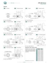
Hydraulic Motor 09 | 14 Tooth Spline Extended 14 Tooth Spline 12/24 Pitch Standard ANSI B92.1-1996 Spline ► A slotted hex nut is standard on this MOUNTING / SHAFT LENGTH CHART tance from the motor mounting is referenced on detailed shaft draw- ings above. ^ Shaft lengths vary ± 0.8 mm [.030 in.] DELIVERING THE POWER TO GET WORK DONE
Open the catalog to page 11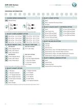
Hydraulic Motor white drive pro ducts ORDERING INFORMATION 1. CHOOSE SERIES DESIGNATION ► The 600 series is bi-directional. Reversing the inlet hose will reverse shaft rotation. 2. SELECT A DISPLACEMENT OPTION 3a. SELECT MOUNT TYPE 3b. SELECT PORT SIZE SIDE MOUNTS ▼ SIDE PORT OPTIONS 11/16" Hole, Aligned Manifold ► Speed sensor option is not available on wheel mounts. 4. SELECT A SHAFT OPTION 14 Tooth Spline Extended ► Extended shafts are designed for use with one of the speed sensor options listed in STEP 7. 5. SELECT A PAINT OPTION Black, Unpainted Mounting Surface 6. SELECT A VALVE CAVITY...
Open the catalog to page 12All White Drive Motors And Steering catalogs and technical brochures
 White Brochure
20 Pages
 OML | OMM Technical Information
32 Pages
 ORBITAL X Technical Information
54 Pages
 OMS Technical Information
53 Pages
 OMSU Technical Information
17 Pages
 OMEW Technical Information
19 Pages
 RE Technical Information
59 Pages
 HP 30 Technical Information
42 Pages
 RS Technical Information
36 Pages
 WS Technical Information
36 Pages
 DH | DS Technical Information
43 Pages
 SbX Technical Information
28 Pages
 OSPM Technical Information
33 Pages
 LAGC Technical-Information
20 Pages
 LAGU Technical-Information
18 Pages
 LAGZ Technical Information
22 Pages
 S10 | S20 Technical Information
39 Pages


Archived catalogs
 OMS
OMS53 Pages
 OMSW
OMSW21 Pages
 VIS 40, 45
65 Pages
 HP 30
HP 3042 Pages
 RS Orbital Motors
36 Pages
 WM
WM8 Pages
 WD
WD14 Pages
 WP
WP18 Pages
 RS Series 200-201
15 Pages
 WR
WR18 Pages
 WG
WG22 Pages
 HB/HK
HB/HK22 Pages
 WS
WS26 Pages
 CE
CE21 Pages
 RE
RE27 Pages
 DT
DT18 Pages
 BK series 913
4 Pages
 SB
SB7 Pages
 FD
FD6 Pages
 2012 Product Catalog
259 Pages
 HB
HB20 Pages
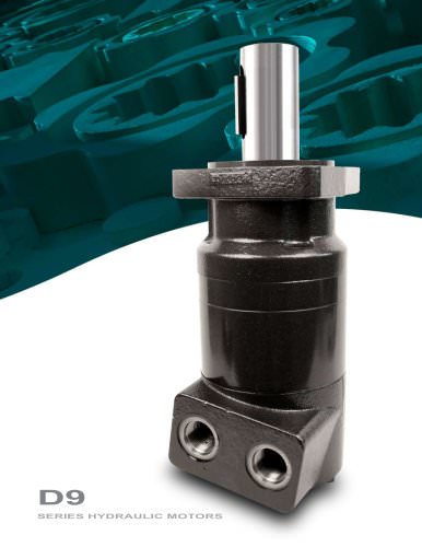
 D9
D914 Pages
 Product Catalog
258 Pages
 FD
FD6 Pages
 BK series 910
4 Pages
 DT
DT20 Pages
 WS
WS22 Pages
 RS D9 Series Hydraulic Motors
16 Pages
 RG Series
32 Pages
 White Hydraulics - Drive products
204 Pages

- Magnetic speed sensor
- Rotational speed sensor
- Flow divider
- Orbital hydraulic motor
- Non-contact speed sensor
- Gear hydraulic motor
- Hydraulic flow divider
- Industrial hydraulic motor
- Compact speed sensor
- Compact hydraulic motor
- High-pressure hydraulic motor
- Robust speed sensor
- Axle steering system
- Variable-displacement hydraulic motor
- High-torque hydraulic motor
- Hydraulic motor for heavy-duty applications
- Low-speed hydraulic motor
- 2-channel flow divider
- Two-speed hydraulic motor