
- Catalogs
- White Drive Motors And Steering
- DR | DT | D9 Technical Information


DR | DT | D9 Technical Information
DR | DT | D9 Technical Information
- Oil Type: Recommended hydraulic oils should have anti-wear, anti-foam, and demulsifying properties. Compatibility with system components is crucial.
- Fluid Viscosity & Filtration: Optimal viscosity is 20 - 43 cSt at operating temperature, with cleanliness at ISO 17-14 or better.
- Installation & Start-up: Ensure proper alignment and avoid using a hammer during installation.
- Motor Protection: Safety precautions for hydraulic motors and motor/brake systems are essential.
- Motor Circuits: Discusses series and parallel connections with a typical motor/brake schematic.
- Product Testing: Includes allowable bearing and shaft loading, and vehicle drive calculations.
- Hydraulic Equations: Provides formulas for power input/output, speed, and torque.
- Shaft Nut Information: Specifications for various tapered shafts.
- Speed Sensors: Features and options for single and dual element sensors.
- Protection Circuitry: Details on internal drain and valve cavity.
- Overview: Features and benefits, typical applications, and specifications.
- Porting: Options include end ported and side ported.
- Series Details: Information on DR 600, 610, 620, 630, and 640 series.
- Overview: Includes standard hydraulic motors and those with wheel hubs.
- Features/Benefits: Lists typical applications and specifications.
- Porting and Housings: Technical information including length and weight charts.
- Overview: Descriptions of all series, features, benefits, and typical applications.
- Specifications: Includes displacement performance for the D9 (800/801 series).
- Technical Information: Covers housings, porting, shafts, and ordering information.
- Grade Resistance (GR): Calculated using GR = (%Grade/100) x GVW.
- Acceleration Force (FA): Determined by FA = (MPH x GVW) / (22 x t).
- Drawbar Pull (DP): Additional force required for towing.
- Total Tractive Effort (TE): Sum of rolling resistance, grade resistance, acceleration force, and drawbar pull.
- Motor Torque (T): Calculated as T = (TE x ri) / (M x G).
- Wheel Slip (TS): Calculated to ensure vehicle performance.
- Steps for calculating forces include determining rolling resistance, grade resistance, acceleration force, and drawbar pull.
- Motor torque and wheel slip calculations are essential for vehicle performance.
- Ensure radial load capacity of motors is sufficient to support the vehicle.
- Consider induced side load when using pulleys or sprockets.
- Use speed sensors with protection circuitry.
- Coefficient of friction values for different surfaces.
- Rolling resistance values for various surfaces.
- Hydraulic equations and multiplication factors for torque and speed calculations.
- Speed sensors offer single and dual element options.
- Protection circuitry in sensors prevents damage.
- Free turning rotor option available for specific applications.
- Heavy-duty roller bearings for high side loads.
- Compact housing for a high power-to-weight ratio.
- Roller Stator® Motor for high torque output.
- Three-Zone Orbiting Valve for exceptional volumetric efficiencies.
- Figures: Illustrate wheel mounts and allowable shaft load/bearing curves.
- Tables: Include bearing load multiplication factor, rolling resistance, and more.
- Specifications and Dimensions: Detailed specifications and dimensions for different models.
- Disclaimer: WHITE reserves the right to alter products without notice.
Catalog excerpts

MOTORS Technical Information
Open the catalog to page 1
White is a leading global provider of motor and steering solutions that power the evolution of mobile and industrial applications around the world.
Open the catalog to page 2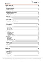
Contents Chapter 1 General data_____________________________________________________________ 6 Oil type _________________________________________________________________________________7 Fluid viscosity & filtration __________________________________________________________________7 Installation & start-up _____________________________________________________________________7 Motor protection _________________________________________________________________________7 Hydraulic motor safety precaution ___________________________________________________________8 Motor/brake precaution __________________________________________________________________________...
Open the catalog to page 3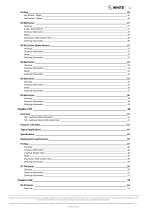
4 Porting _________________________________________________________________________________26 End Ported – Offset _____________________________________________________________________________ 26 Side ported – Radial ____________________________________________________________________________ 26 DR 600 Series ___________________________________________________________________________27 Housings _____________________________________________________________________________________ 27 4-hole, Wheel Mount ___________________________________________________________________________ 27 Technical Information...
Open the catalog to page 4
5 Series Descriptions _____________________________________________________________________________ 53 Features/ Benefits ______________________________________________________________________________ 53 Typical Applications _____________________________________________________________________________ 53 Specification __________________________________________________________________________________ 54 Displacement Performance _______________________________________________________________________ 54 D9 (800/801 Series) ______________________________________________________________________59...
Open the catalog to page 5
Chapter 1 General dataTopics: • Oil type • Fluid viscosity & filtration • Installation & start-up • Motor protection • Hydraulic motor safety precaution • Typical Motor/Brake Schematic • Motor circuits • Product testing • Allowable bearing & shaft loading • Vehicle drive calculations • Induced side load • Hydraulic equations • Speed sensors • Protection circuity • Internal drain • Valve cavity WHITE can accept no responsibility for possible errors in catalogues, brochures, and other printed material. WHITE reserves the right to alter its products without notice. This also applies to products...
Open the catalog to page 6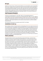
Oil type Hydraulic oils with anti-wear, anti-foam and demulsifies are recommended for systems incorporating these motors. Straight oils can be used but may require VI (viscosity index) improvers depending on the operating temperature range of the system. Other water based and environmentally friendly oils may be used, but service life of the motor and other components in the system may be significantly shortened. Before using any type of fluid, consult the fluid requirements for all components in the system for compatibility. Testing under actual operating conditions is the only way to determine...
Open the catalog to page 7
Hydraulic motor safety precaution A hydraulic motor must not be used to hold a suspended load. Due to the necessary internal tolerances, all hydraulic motors will experience some degree of creep when a load induced torque is applied to a motor at rest. All applications that require a load to be held must use some form of mechanical brake designed for that purpose. Motor/brake precaution Caution! The motors/brakes are intended to operate as static or parking brakes. System circuitry must be designed to bring the load to a stop before applying the brake. Caution! Because it is possible for some...
Open the catalog to page 8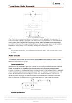
Typical Motor/Brake Schematic Figure 1 Typical Motor/ Brake schematic Once all system connections are made, one release port must be opened to atmosphere and the brake release line carefully charged with fluid until all air is removed from the line and motor/brake release cavity. When this has been accomplished the port plug or secondary release line must be reinstalled. In the event of a pump or battery failure, an external pressure source may be connected to the brake release port to release the brake, allowing the machine to be moved. Note: It is vital that all operating recommendations be...
Open the catalog to page 9
10 In a parallel connection all of the motor inlets are connected. This makes the maximum system pressure available to each motor allowing each motor to produce full torque at that pressure. The pump flow is split between the individual motors according to their loads and displacements. If one motor has no load, the oil will take the path of least resistance and all the flow will go to that one motor. The others will not turn. If this condition can occur, a flow divider is recommended to distribute the oil and act as a differential. Figure 3 Parallel connection Note: The motor circuits shown...
Open the catalog to page 10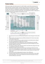
Product testing Performance testing is the critical measure of a motor’s ability to convert flow and pressure into speed and torque. All product testing is conducted using a state of the art test facility. This facility utilizes fully automated test equipment and custom designed software to provide accurate, reliable test data. Test routines are standardized, including test stand calibration and stabilization of fluid temperature and viscosity, to provide consistent data. The example below provides an explanation of the values pertaining to each heading on the performance chart. Figure 4 Product...
Open the catalog to page 11
Allowable bearing & shaft loading This catalog provides curves showing allowable radial loads at points along the longitudinal axis of the motor. They are dimensioned from the mounting flange. Two capacity curves for the shaft and bearings are shown. A vertical line through the centerline of the load drawn to intersect the x-axis intersects the curves at the load capacity of the shaft and of the bearing. In the example below the maximum radial load bearing rating is between the internal roller bearings illustrated with a solid line. The allowable shaft rating is shown with a dotted line. The...
Open the catalog to page 12All White Drive Motors And Steering catalogs and technical brochures
 White Brochure
20 Pages
 OML | OMM Technical Information
32 Pages
 ORBITAL X Technical Information
54 Pages
 OMS Technical Information
53 Pages
 OMSU Technical Information
17 Pages
 OMEW Technical Information
19 Pages
 RE Technical Information
59 Pages
 HP 30 Technical Information
42 Pages
 RS Technical Information
36 Pages
 WS Technical Information
36 Pages
 DH | DS Technical Information
43 Pages
 SbX Technical Information
28 Pages
 OSPM Technical Information
33 Pages
 LAGC Technical-Information
20 Pages
 LAGU Technical-Information
18 Pages
 LAGZ Technical Information
22 Pages
 S10 | S20 Technical Information
39 Pages

Archived catalogs
 OMS
OMS53 Pages
 OMSW
OMSW21 Pages
 VIS 40, 45
65 Pages
 HP 30
HP 3042 Pages
 RS Orbital Motors
36 Pages
 WM
WM8 Pages
 WD
WD14 Pages
 WP
WP18 Pages
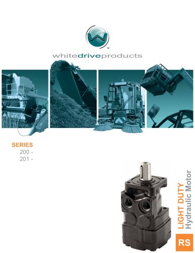 RS Series 200-201
15 Pages
 WR
WR18 Pages
 WG
WG22 Pages
 HB/HK
HB/HK22 Pages
 WS
WS26 Pages
 CE
CE21 Pages
 RE
RE27 Pages
 DR
DR23 Pages
 DT
DT18 Pages
 BK series 913
4 Pages
 SB
SB7 Pages
 FD
FD6 Pages
 2012 Product Catalog
259 Pages
 HB
HB20 Pages
 D9
D914 Pages
 Product Catalog
258 Pages
 FD
FD6 Pages
 BK series 910
4 Pages
 DT
DT20 Pages
 WS
WS22 Pages
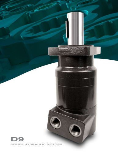 RS D9 Series Hydraulic Motors
16 Pages
 RG Series
32 Pages
 White Hydraulics - Drive products
204 Pages

- Magnetic speed sensor
- Rotational speed sensor
- Orbital hydraulic motor
- Gear hydraulic motor
- Non-contact speed sensor
- Industrial hydraulic motor
- Hydraulic flow divider
- Compact speed sensor
- Compact hydraulic motor
- High-pressure hydraulic motor
- Axle steering system
- Robust speed sensor
- High-torque hydraulic motor
- Variable-displacement hydraulic motor
- Hydraulic motor for heavy-duty applications
- Low-speed hydraulic motor
- 2-channel flow divider
- Two-speed hydraulic motor