
- Catalogs
- White Bream
- Junction Box

Junction Box
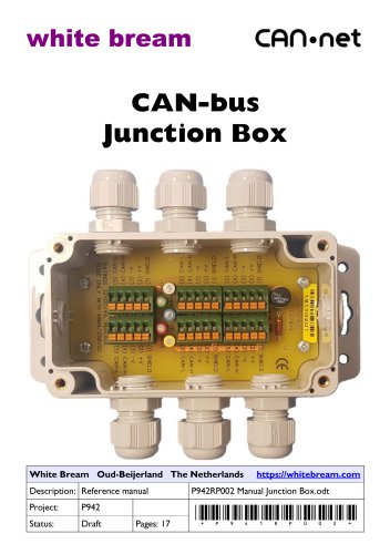
Junction Box
- Disclaimer: White Bream products require written approval for critical applications. The buyer assumes all risks.
- Trademarks & Copyrights: Trademarks are owned by their respective owners.
- Warranty: Two-year warranty against defects, excluding misuse or modifications.
- Liability: White Bream is not liable for damages from misuse or inability to use the product.
Overview
The CAN-bus Junction Box is designed for long-distance, low-speed installations, supporting up to 6 or 12 cable segments. It features a polycarbonate enclosure with IP67/NEMA4X rating and an integrated termination resistor for easy configuration and diagnostics.
Specifications
- Hardware: Supports up to 32VDC, 4ADC, with 5-pin spring clamp terminals and IP65 ingress protection. Optional CANopen® M12 connectors are available.
- Connections: Spring clamp terminals accommodate 0.5 to 2.0 mm² wires, with optional CANopen® M12 pluggable connections.
- Environmental: Operates from -20 to +75°C, with 100% humidity tolerance.
- Dimensions: Available in 6-way and 12-way configurations with specific enclosure sizes.
Installation
- Mount on a flat surface and ensure proper cable gland sealing to maintain ingress protection.
- Use specified wire sizes and ensure proper termination of shielded cables.
- Follow specific instructions for ATEX applications, including temperature considerations and intrinsically safe circuits.
Ordering Information
- Includes part numbers and descriptions for 6-way and 12-way junction boxes, including ATEX versions.
Document Revisions
- Details changes in document revisions, including added sections and updated drawings.
Annex A: Declaration of Conformity
The product complies with ATEX, EMC, LVD, and RoHS directives, verified through various EN standards.
Technical Documentation Overview: The document relates to the EN 50581:2012 standard, outlining technical documentation for assessing electrical and electronic products concerning hazardous substances restrictions.
FCC Compliance: The CAN-bus Junction Box complies with Part 15 of the FCC Rules, ensuring it does not cause harmful interference and accepts any interference received. It meets Class B digital device limits for residential installations.
Interference Mitigation Measures: Users are advised to reorient or relocate the receiving antenna, increase separation between equipment and receiver, connect to a different circuit, or consult a technician if interference occurs.
Contact Information: White Bream is located at L.J. Costerstraat 13d, 3261LH Oud-Beijerland, The Netherlands. More information is available on their websites: whitebream.com and whitebream.nl.
Catalog excerpts
CAN-bus Junction Box Reference manual Draft White Bream © 2017-2019 page 2 P941RP002
Open the catalog to page 2
Reference manual Preface Disclaimer White Bream products are not authorized for use in, or in connection with surgical implants, or as critical components in any medical or nuclear, or aircraft, or other transportation devices or systems where failure to perform can reasonably be expected to cause significant injury to the user, without the express written approval of an executive officer of White Bream. Such use is at buyer's sole risk, and buyer is responsible for verification and validation of the suitability of products incorporated in any such devices or systems. Buyer agrees that White...
Open the catalog to page 3
Reference manual CAN-bus installations running at long distances and low speeds can use fairly long stub lines. This allows for a simpler wiring topology where the different nodes can be placed up to 5 meters away from the 'backbone'. Particularly on long distances, this is extra beneficial because the effective length of the CAN-bus can remain shorter, which saves on wiring cost and - more importantly - reduces voltage drops along the line. To aid such install, we have this field bus distribution box, which allows for up to 6 or 12 cable segments to be joined together. This is done with 5-pole...
Open the catalog to page 4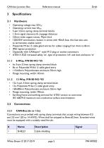
CAN-bus Junction Box Reference manual Draft 3.1 Hardware • Operating voltage max 32VDC • Operating current max 4ADC • 5-pin 3.5mm spring clamp terminal blocks • 1.3mm signal clearance & creepage distances • 2.0mm wide copper traces, 70^lm thick • 120Q/2W termination resistor in series with 40mA fuse, this fuse also acts as termination enable switch • Polyamide M16x1.5 cable gland entries for cables ranging from 4mm to 8mm • IP65 ingress protection • Optionally with CANopen® style M12 plug or socket connectors • ATEX II 3GD increased safety 'ec', type of protection 'nA' and dust enclosure 'tc'...
Open the catalog to page 5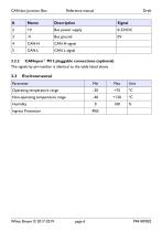
CAN-bus Junction Box Reference manual Draft White Bream © 2017-2019 page 6 P94IRP002
Open the catalog to page 6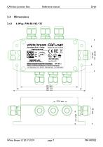
CAN-bus Junction Box Reference manual Draft white bream Cfifl«net Junction Box 12-way □w^Kinw) « mvw> in Maund CChF GURATIOI'J IHEawnMB'n«c ISDEitr 1C TIOTCOi linh Jl- fc+rs-fi LI. Lo!tcri*j ui IJL' J26ILH Ou&Bcjcrland I he Nc'J'o jnci White Bream © 2017-2019 page 7 P94IRP002
Open the catalog to page 7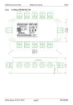
Reference manual
Open the catalog to page 8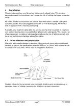
Reference manual Mount the junction box on a flat surface with properly aligned holes. This prevents excessive stresses in the enclosure and reduces the risk of voiding the ingress protection rating. All M16x1.5 holes in the junction box shall be fitted with either a suitable cable-gland containing a cable, M12-style pluggable connection or M16 blanking plug. All of which shall be equipped with a matching sealing ring. If possible, only install the cables after the junction box has been mounted. At very least wait until the box has been mounted before tightening the cable glands. This reduces...
Open the catalog to page 9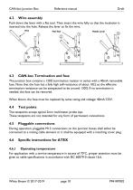
Reference manual Wire assembly Push down the lever with a flat tool. Then insert the wire fully so that the insulation is inserted into the hole. Release the lever to fix the wire. CAN-bus Termination and fuse The junction box contains a 120Ω termination resistor in series with a 40mA removable fuse. Note that the fuse has a faily high self-resistance of about 10Ω, so the effective termination resistance can be extepected to be around 130Ω. If no termination is needed, the fuse can be removed. When blown, the fuse must be replaced by same rating and voltage; 40mA/125V. Test points The testpoints...
Open the catalog to page 10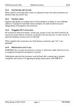
Reference manual 4.6.2 Intrinsically safe circuits When used for intrinsically safe circuits, no exposed circuits with other protection are allowed inside the junction box. 4.6.3 Flexible cables Supplied cable glands are suitably only for fixed installation of cables. In case of flexible cables, for example for hand-held control pendants, the cable should be secured independently of the glands in the enclosure. 4.6.4 Pluggable M12 connection All connections shall be of female / socket type, except at most one which shall then be used as the power feed for all devices connected to the junction...
Open the catalog to page 11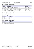
CAN-bus Junction Box Reference manual Draft White Bream © 2017-2019 page 12 P941RP002
Open the catalog to page 12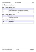
CAN-bus Junction Box Reference manual Draft White Bream © 2017-2019 page 13 P941RP002
Open the catalog to page 13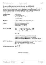
CAN-bus Junction Box Reference manual Draft Annex A: Declaration of Conformity for ATEX/CE The manufacturer hereby declares that this product is according to the requirements of annex II of the EEC directive 2014/34/EC regarding ATEX and directive 2014/30/EU regarding electromagnetic compatibility (EMC), directive 2014/35/EU regarding low voltage equipment (LVD) and directive 2011/65/EU regarding RoHS. CAN-bus Junction Box Reference manual Draft Product: Model: ATEX Marking: White Bream L.J. Costerstraat 13d 3261LH, Oud-Beijerland The Netherlands 6-Way / 12-Way 5-pin CAN Junction box 80-942-203...
Open the catalog to page 14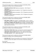
CAN-bus Junction Box Reference manual Draft This product has been found in conformity with directive 2014/34/EU (ATEX) by testing and verification with the following standards: • EN 60079-0:20l2/AI 1:2013 Explosive atmospheres - Part 0: General requirements • EN 60079-7:201 5 Explosive atmospheres - Part 7: Equipment protection by increased safety "e" • EN 60079-15:2010 Explosive atmospheres - Part 15: Equipment protection by type of protection "n" • EN 60079-31:2014 Explosive atmospheres - Part 31: Equipment dust ignition protection by enclosure "t" This product has been found in comformity...
Open the catalog to page 15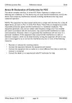
Reference manual Annex B: Declaration of Conformity for FCC This device complies with Part 15 of the FCC Rules. Operation is subject to the following two conditions: (1) This device may not cause harmful interference, and (2) this device must accept any interference received, including interference that may cause undesired operation. NOTE: This equipment has been tested and found to comply with the limits for a Class B digital device, pursuant to Part 15 of the FCC Rules. These limits are designed to provide reasonable protection against harmful interference in a residential installation. This...
Open the catalog to page 16
- Digital I/O
- IO module
- Analog I/O
- Digital IO module
- Industrial gateway
- Ethernet gateway
- Humidity and temperature probe
- Polymer junction box
- Analog IO module
- Wireless gateway
- IP67 junction box
- Diode
- PC terminal box
- Digital humidity and temperature sensor
- Communication interface card
- NEMA junction box
- Metal terminal box
- NEMA 4X junction box
- Voltage diode