- Company
- Products
- Catalogs
- News & Trends
- Exhibitions
catalog
1 /24Pages

catalog
1 /24Pages
Catalog excerpts

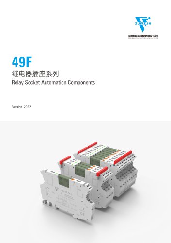
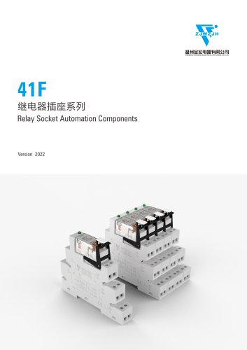
www.wzjh.ee Ac Isolated Switch Automation Components I/O Wenzhou Jinhong Electrical Appliance Co.,ltd '
Open the catalog to page 1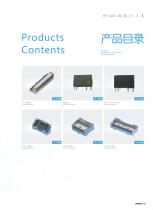
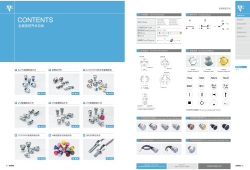
Products Contents Security, we want you to be more comprehensive. -» P.299 (PANASONIC) Ac Isolated Switch
Open the catalog to page 2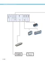
SlftS^S/System structure diagram
Open the catalog to page 3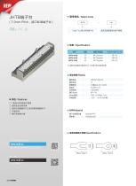
^^npS / Select Code ■SIAM Polycarbonate
Open the catalog to page 5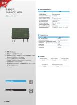
D lf®!i*J±4,000V ' It^ffiAC 2,000V(^H?Ptt!^(Bl)fl5 *iCt£T(PANASONIC) PA *££§§ □ SwitchingJSBra»SSa*ai%» 100 nS, lOOmVDC-5A250VACx 5A30VDC (Made inChina)
Open the catalog to page 7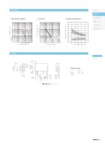
±0.12 Bottom view JINHONG 302
Open the catalog to page 8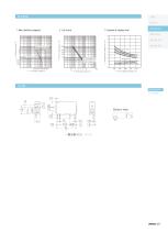
1. Max. switching capacity 2. Life Curve 3. Operate & release time PANASONIC ► Contact voltage, V -► Switching capacity, A ±0.12 Bottom view JINHONG 304
Open the catalog to page 10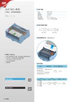
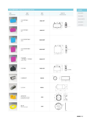
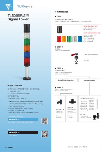
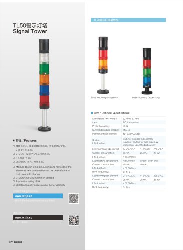
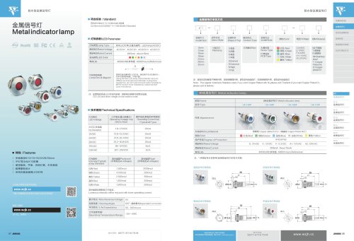
■ ss[&sMifc£/£ ■ $#14 / Features □ /Mai6*. (90.6(W) X70.0(D) X39.5(H)) □ Channel^fflip^ □ Btttm
Open the catalog to page 13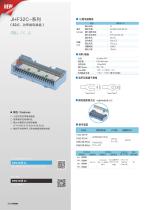
Contact SSi£%ffi rr Coil www.wijh.ee Common Interface ittnnnRTt itt.'S
Open the catalog to page 15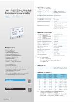
/ Contact Data JH41F Subminiature power relay cTC.» ^ @> C€ MrSJBS/Contact arrangement Sli^Bi/Contact resistance litSWfl/Contact material ftt'SStSsd&tt)/Contact rating (Res.load] Max. switching voltage switching current switching power IH;WSnp/Mechanical endurance S^Wnp/Electrical endurance tfeUffiES/lnsulation resistance SSHfflfttj&IB] Between coil & contacts Between open contacts Sjf'E Btfl'a] / Operate time(at nomi.volt.) fKftBftl'H] / Release time(at nomi.volt.) /ti ^iStt/Functional Shock resistance 35/t/Destructive JSitj/Vibration resistance ■ f§tt / Features □ ^^M(®(R5mm) □ em&tmmti □ ^s%si^fiitiijas®a6kv □...
Open the catalog to page 17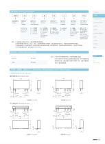
Coil Contact Version voltage arrangement Construction Contact material Contact Customer plating Special code 8: tKTSS 36: mmsm 8: Flat pack version Nil: Vertical version S: S: Plastic sealed Nil: Flux proofed G: 35: 7FS1& G: Gold plated Nil: No gold plated ©Ml: (210) =s70%g5ffiEfi HWF'S. E.g(210) stands for pick-up voltage less than 70% of nominal voltage / Safety Approval ratings UL/CUL Pending £H12IIL ^SbIIL / Dimensions, Wiring diagram and PC Board Layout □ ^H^K^/Outline Dimensions HHS^H/Vertical version
Open the catalog to page 18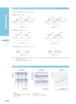
□ S^7L/^vI'(JrI!0@) /PCB Layout(bottom view) SliSr^H/Vertical version 2-01 ±0.1 2-01-3*01 fifijS^ffi(V) Contact Voltgae Percentage of Nominal Coil Voltage NO,AgNi,Ri1tSl^, 250VAC, KtflftJM, NO, AgNi, Resistive load, 250VAC, jgsg, 1 siS9sBr0 FI ux proofed, Room temp., 1 s on 9s off.
Open the catalog to page 19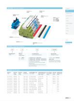
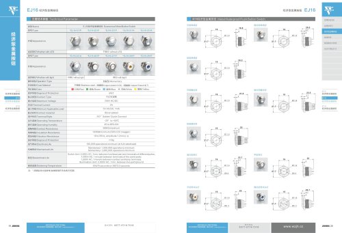
flMaes? ***** Type Contact c2:«usc?itu*, «$h£$s, C4:3iRSC3l!UW. #Sl5S££, A: PCB terminal, PCB mounting C2: Screw terminal, DIN rail mounting, with linger protection device C4: Spring-loaded teiminal, DIN rail mounting, with linger protection device 1,2,3,4,5: WUl wraram" See table abovefor corresponding information with relay’s coil voltage t£IS#^/Specifications JESSl? Type
Open the catalog to page 20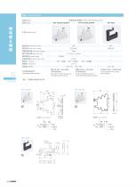
41F-1Z-C2/172/3/4/5 SaSiliSraflJiJS/Ultra-thin Relay socket 41F-1Z-C4/1Z2/3/4/5 /Nominal current ISS/E^Hi /Nominal voltage WR^Ss'RJS/Wire strip Length U^^SbIbIII /Max wire size tltTJfljE /Screw torque /Suitable relay type StiUtt* /Jumper PIS®* /Separator ®iR®* /Maker Termination&mounting Ultras I iiiw, Screw terminal, DIN rail mounting, with finger protection device ssttssiasis, ^tirassi, Spring-loaded terminal, DIN rail mounting, with f nger protection device EPH®SSIiiiS. EPHSaSSt Printing plate terminal, printing plate installation
Open the catalog to page 21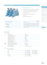
■ Interface Module 41F □ Relay module up to 6 A 250 V, different contact materials □ Solid state modules for most loads DC and AC up to 2 A □ Coil UC = AC/DC, no protection circuit required □ LED status display □ Screw terminals or cage clamp terminals □ Jumper link □ Super small mounting: 6,2 mm 41F Interface module For PLC's and process control.high power contact AgNi With screw terminals(41 F-1Z-C2)or cage clamp terminals (41F-1Z-C4).Recommended max.load 250 V6A resistive. Jumper link optional. ■ Specifications □ Technical Data Contact Switching current lTH Recommended minimal load Switch...
Open the catalog to page 22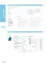
□ 41F Combo with cage clamp terminals Nominal coil voltage 12V 24V 18V 60V 110-125V 220-240V Technical data Rated current (per signal path) 1A Minimum required supply power 3W Control logic Positive switching (to A) Power supply status indication Green LED Ambient temperature range ^Ot'+ZOT: Terminals for 24V control logic Type of connector 14 pole, according to Terminals for 24V Power supply Wire strip length 9.5mm Max.wiresize solid wire
Open the catalog to page 23Archived catalogs
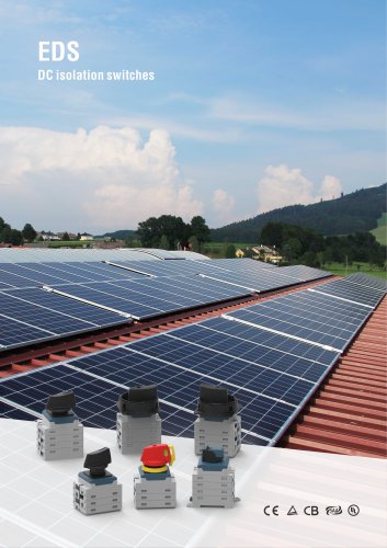
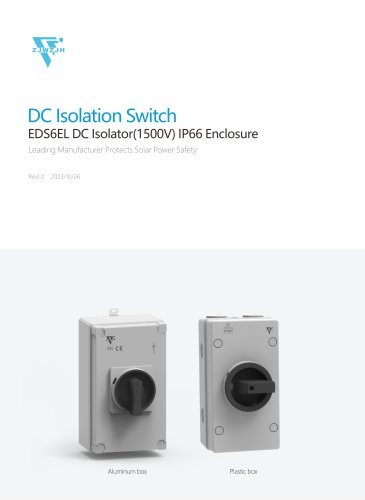 eds EDS6EL 1500v
6 Pages
 foot switch
6 Pages
 relay base 49F-1Z-C6
5 Pages
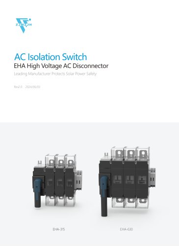
 AC ISOLATOR SWITCH JHAS69
12 Pages
 isolated switch
15 Pages
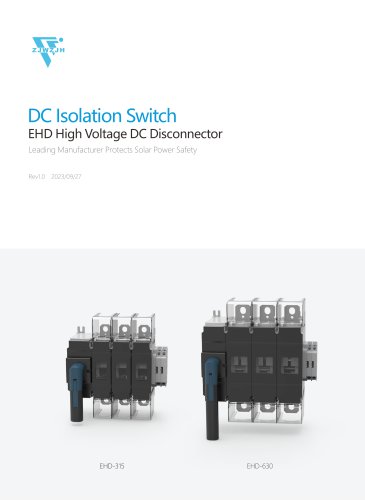
 DC SWITCH
11 Pages
 SLIM RELAY BASE 2Z
5 Pages
 Accessories
1 Page
 9214597311605365
8 Pages
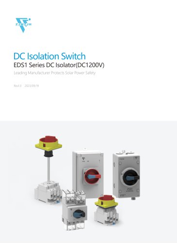 DC switch
8 Pages
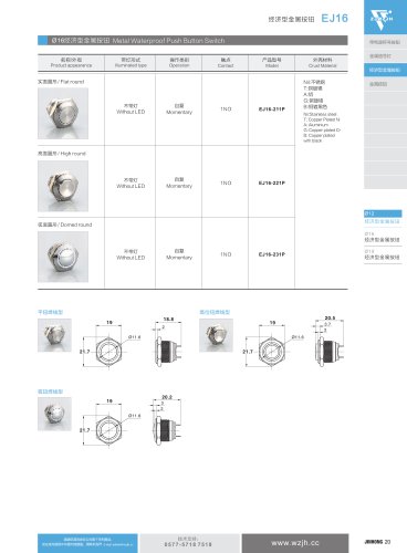
 Metal Pushbutton Switch
1 Page
 Metal pushbutton
1 Page
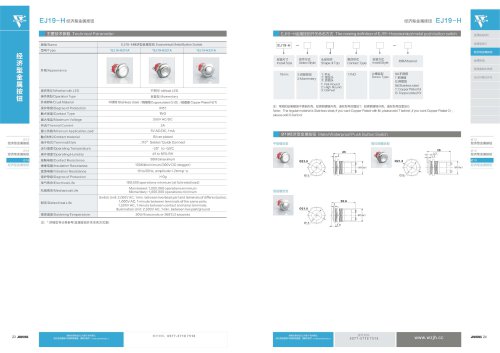 EJ19-H series
1 Page
 J19 Series
1 Page
 WZJH Relay and Socket
37 Pages
 EJ12 Series
1 Page
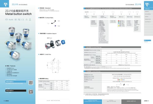 22j16
22j161 Page
 ISOLATING SWITCH
18 Pages
 50MM STACK LIGHT
3 Pages
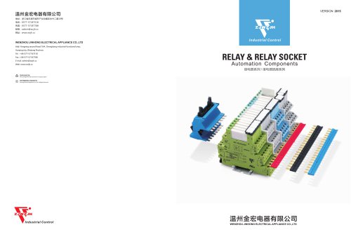
 RELAY & RELAY SOCKET
58 Pages
 EJ12&J12 Metal button switch
9 Pages
 22J16 Metal button switch
6 Pages
 JH
JH1 Page
 SIGNAL TOWER
3 Pages
 JHAS69
1 Page
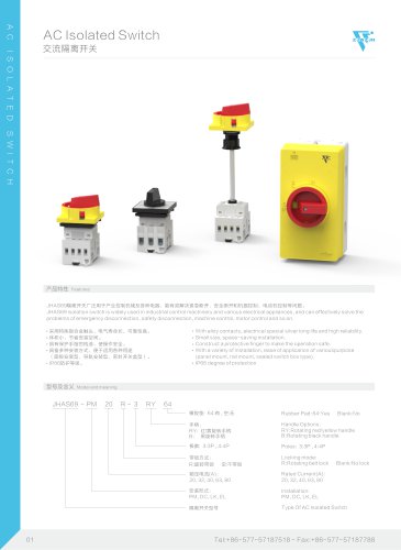
 Ac Isolated Switch
24 Pages
 LW20/23/63SERIES
6 Pages


- Single-pole switch
- Push-button switch
- Switching relay
- Technology switch
- Protection relay
- Isolator switch
- Multipole switch
- Electromechanical switch
- Control pedal
- Electromechanical relay
- Safety electric switch
- Single pedal pedal
- Time relay
- Electronic pedal
- Rotary electric switch
- DC electromechanical relay
- BIO-UV stack light
- IP67 switch
- Multipole disconnect switch
- LED indicator light