- Company
- Products
- Catalogs
- News & Trends
- Exhibitions
INTT203
1 /2Pages

INTT203
1 /2Pages
Catalog excerpts

Inductive Sensor for Extreme Temperature Ranges Technical Data Inductive Data Switching Distance Correction Factors Stainless Steel V2A/CuZn/Al Standard Target Mounting Mounting A/B/C/D in mm Mounting B1 in mm Switching Hysteresis Electrical Data Supply Voltage Supply Voltage with IO-Link Switching Frequency Temperature Drift Sensor head temperature range Temperature range of the plug Number of Switching Outputs Switching Output Voltage Drop Switching Output/Switching Current Residual Current Switching Output Short Circuit Protection Reverse Polarity and Overload Protection Analysis module integrated into M12 sensor connector Easy to replace sensors with data storage feature Highly efficient with an average service life of 5 years Three configurable switching distances: 15/20/25 mm Protection Class Service Life (T = +200 °C) Service Life (T = +250 °C) Mechanical Data Stainless steel V2A; PEEK; PTFE CuZn, nickel-plated Degree of protection of the plug Degree of protection, sensor head Outer diameter cable PWIS-free Safety-relevant Data Error Indicator Programmable switching distance Error Output PNP NO/NC antivalent Connection Diagram No. Control Panel No. Suitable Connection Equipment No. Suitable Mounting Technology No. Complementary Products IO-Link Master Inductive Sensors Plug material Sensor head material The high temperature inductive sensor with cable lengths of 1 to 30 meters can be positioned as needed in hot areas of systems and machines. Installation is also easy due to the ultra-compact design, as the analysis module is integrated into the M12 sensor connector. The sensor thus takes up far less space and is highly compatible thanks to its standardized design. The weproTec technology makes it possible to install the sensors directly next to or across from one another. In addition, sensor parameters like switching distance and output functions can be configured individually via IO-Link.
Open the catalog to page 1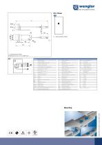
Ctrl. Panel 01 = Switching Status Indicator 1 = Switching Status Indicator All dimensions in mm (1 mm = 0.03937 Inch) Legend + – ~ A Ā V E T Z S RxD TxD RDY GND CL E/A Supply Voltage + Supply Voltage 0 V Supply Voltage (AC Voltage) Switching Output (NO) Switching Output (NC) Contamination/Error Output (NO) Contamination/Error Output (NC) Input (analog or digital) Teach Input Time Delay (activation) Shielding Interface Receive Path Interface Send Path Ready Ground Clock Output/Input programmable PoE IN OSSD Signal BI_D+/– EN0 RS422 PT ower over Ethernet Safety Input Safety Output Signal Output...
Open the catalog to page 2All Wenglor sensoric GmbH catalogs and technical brochures
 P1KH008
2 Pages
 WP04NAT80
2 Pages
 OY1TA603P0003
2 Pages
 P1KY001
2 Pages
 ZAI02PN02
2 Pages
 I08H016
2 Pages
 TIF352U0089
2 Pages
 FIS-0003-0104
2 Pages
 FFAT046
2 Pages
 FFAF002
2 Pages
 CP35MHT80
2 Pages
 CP24MHT80
2 Pages
 CP08MHT80
2 Pages
 CP25QXVT80
2 Pages
 Inductive Sensors
6 Pages
 weFlux²
9 Pages
 Top Performance in 2D and 3D
44 Pages
 Light Curtains
4 Pages
 InoxSens
94 Pages
 S2DF004
2 Pages
 Product Flyer Ultrasonic
5 Pages
 Brochure 2D/3D Sensors
44 Pages
 IO-Link Catalog
121 Pages
 Corporate Brochure
15 Pages
 weQube
24 Pages
 Industrial Communication
8 Pages
 Catalog Fluid Sensors
50 Pages
 Inox Sens Catalog
86 Pages
 New Standards for Precision
6 Pages


- Digital imager
- Temperature probe
- Visible imager
- Ethernet switch
- CMOS camera module
- Industrial network switch
- LED lighting
- Infrared imager
- Process software
- Full-color camera system
- Proximity switch
- Managed switch
- Push-button switch
- Waterproof network switch
- Pressure probe
- Image processing camera module
- Monitoring software solution
- Monochrome camera module
- Cylindrical proximity sensor
- Communication gateway