- Catalogs
- Weilong Intelligent Technology (Dongguan) Co., Ltd.
- WL490 DC Rotary Solenoid Selection Guide


- Company
- Products
- Catalogs
- News & Trends
- Exhibitions
WL490 DC Rotary Solenoid Selection Guide
WL490 DC Rotary Solenoid Selection Guide
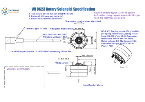
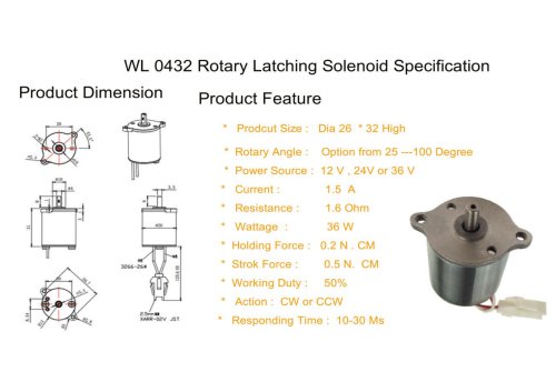
DC rotary solenoids are electromagnetic actuators designed for applications requiring rotary motion rather than linear motion. They are compact, powerful, and suitable for various applications due to their ability to operate under any DC voltage level. These solenoids are durable, easy to maintain, and adjust, making them highly demanded across industries, including medicine and automation, where space is limited but high torque is needed.
DC rotary solenoids function by passing current through a coil, creating a magnetic field that causes the rotor to rotate to a specified angle. This rotation is facilitated by special slots or helical grooves that convert magnetic power into rotational movement. A return mechanism ensures the rotor returns to its original position when power is disconnected.
DC rotary solenoids have diverse applications across various sectors. In industry, they are integral to sorting systems, packaging machines, and robotics. They are also used in smart locks, safes, and access control systems for rapid and effective operation. Automotive uses include vent systems, fluid management, and door locks. In the medical field, they are found in diagnostic tools and machinery. Additionally, they regulate airflow in air conditioning systems and are used in cameras and optical devices.
Catalog excerpts

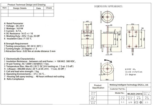
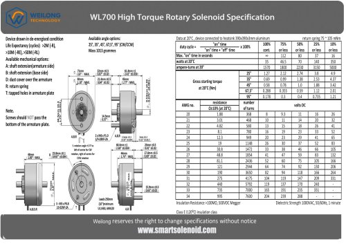
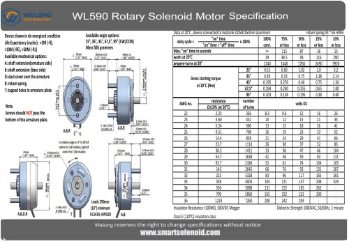
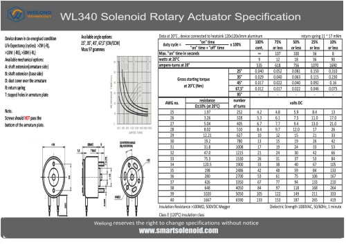
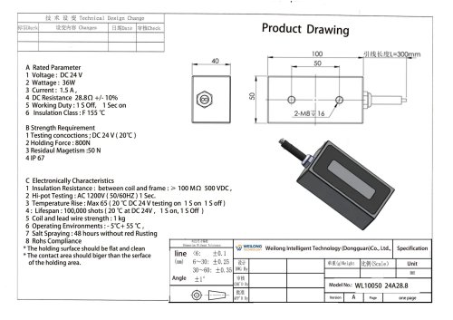
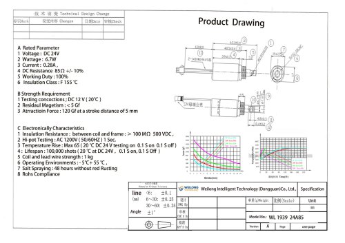
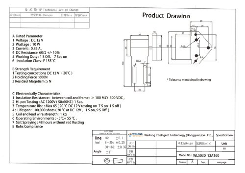
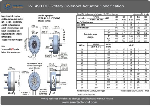
Device drawn in de-energised condition Life Expectancy (cycles): >2M (-R), >10M (-RE), >50M (-RL) Available mechanical options: A: shaft extension(armature side) 8: shaft extension (base side) D: dust cover over the armature R: return spring T: tapped holes in armature plate Note. Screws should NOT pass the bottom of the armature plate. Available angle options: Data at 20°C, device connected to heatsink 190x190x3mm a Insulation Resistance >100MQ, 500VDC Megger Dielectric Strength 1000VAC, 50/60Hz, 1 minute Class E (120°C) insulation class Weilong reserves the right to change specifications without notice
Open the catalog to page 1
WL490 DC Rotary Solenoid Selection Guide DC Rotary Solenoid Actuator short Description It is a type of electromagnetic actuator that can operate under direct current, producing rotary motion instead of linear one, thus making it suitable for applications where linear motions are unnecessary. A DC rotary solenoid provides a compact and powerful actuator to make some components rotate around some point. It can operate under the action of any DC voltage level, being very durable and having easy maintenance and adjustment capabilities. Being highly demanded in industries and everyday life, it is...
Open the catalog to page 2
Electromagnetic force converts linear motion -> rotary motion. Spring return or bistable rotation system. • Coil energization creates magnetic field. • The armature rotates via torque conversion mechanism. Rotation angle: 45°, 90°, etc. High torque density, Fast response time, Long cycle life. Automated locks. • Compact & durable design, • Precise control, • Valve control, • Sorting systems, • Medical devices, • Aerospace mechanisms.
Open the catalog to page 3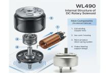
WL490Internal Structure of DC Rotary SolenoidMain Components (Numbered Callouts) 1. Coil winding (copper wire) 2. Iron core / housing 3. Rotor armature return spring system 4. Output bearing support design
Open the catalog to page 5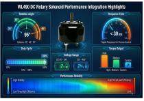
Response Time Rapid Response for Precise Control Torque Output Voltage Range Performance Stability
Open the catalog to page 6
0 Required rotation angle (30°/ 45° / 90°) |\^ Voltage compatibility (DC 12V / 24V / custom) 0 Duty cycle requirement Installation space limitation Force/torque requirement Expected lifetime cycles
Open the catalog to page 8All Weilong Intelligent Technology (Dongguan) Co., Ltd. catalogs and technical brochures
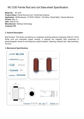 WL1230 Rod Core Ferrite Coil
3 Pages
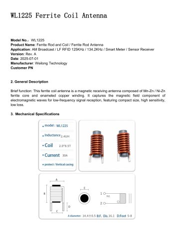 WL1225 Ferrite Coil Antenna
3 Pages
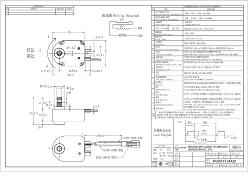 WL0616 Holding Solenoid
8 Pages
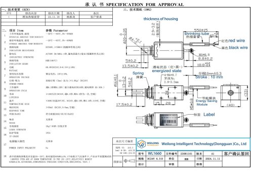 WL3031 Holding electromagnet
8 Pages
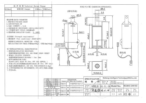 WL 0643 Pull Solenoid
7 Pages
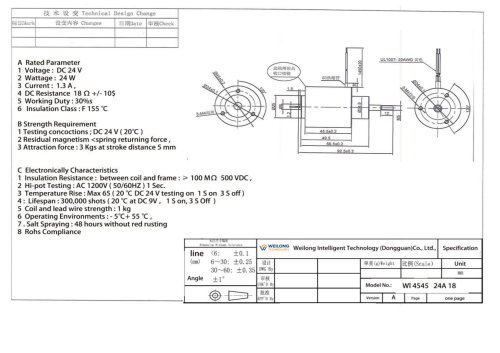 WL4545 push pull solenoid DC
8 Pages