- Catalogs
- Weilong Intelligent Technology (Dongguan) Co., Ltd.
- WL4020 Industrial Push Pull Magnetic Solenoid Guide


- Company
- Products
- Catalogs
- News & Trends
- Exhibitions
WL4020 Industrial Push Pull Magnetic Solenoid Guide
WL4020 Industrial Push Pull Magnetic Solenoid Guide
- Automation Machinery: Utilized in mechanical locks, sortation systems, robotic arms, conveyors, and automatic doors.
- Vending Machines and Smart Lockers: Acts as a locking mechanism.
- Medical Equipment: Compact and highly accurate solenoids are used for precision tasks.
- Automobiles: Operates fuel, transmission, or other electronic locking systems.
- Household Appliances: Found in coffee machines, printers, and smart home equipment for switching and dispensing functions.
- Textile and Packaging Machinery: Provides precise linear motion in repetitive applications.
- Aerospace and Military Equipment: Controls aircraft landing gears and gun firing mechanisms.
Catalog excerpts
WL4020 Industrial Push Pull Magnetic Solenoid Guide The Push pull magnetic solenoid is widely applied in a variety of industrial and commercial products for controlling linear motion. The typical applications are in the automation machinery, including mechanical lock, sortation system, robotic arm, conveyor, and automatic door. The fast response makes them suitable for high-speed machines. They can be found in vending machines and smart lockers as locking mechanisms. Compact and highly accurate solenoids can be found in a wide variety of medical equipment. They are also widely used in automobiles to operate fuel, transmission, or other electronic locking systems. High-performance push pull magnetic solenoid can be found in coffee machines, printers, smart home equipment, and other household appliances as a switching and dispensing function. Push pull solenoids can also be found in textile machinery and packaging machinery for providing precise linear motion in repetitive applications. Specialized push pull solenoids can be found in aerospace and military equipment for controlling aircraft landing gears or gun firing mechanisms.
Open the catalog to page 1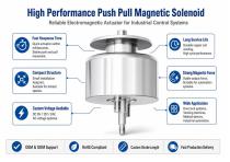
Compact Structure Small installation footprint, Suitable for limited spaces. Strong Magnetic Force Stable output force, Suitable for automation system s. O Custom Voltage Available Wide Application Door lock systems, Vending machines, Medical devices, Industrial automation.
Open the catalog to page 2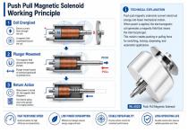
I Push Pull Magnetic Solenoid Working Principle TECHNICAL EXPLANATION Coil Energized Push pull magnetic solenoids convert electrical energy into linear mechanical motion. When power is applied, the electromagnetic coil generates a magnetic field that moves the internal plunger. This motion creates pushing or pulling force for switching, locking, dispensing, and automation applications. Q Plunger Movement Plunger moves forward or backward (push/pull) to generate force. When power is turned off, the magnetic field disappears. The internal spring returns the plunger to its original position. Push...
Open the catalog to page 3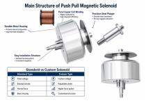
Durable Metal Housing • Protects internal components , • Improves heat dissipation Easy Installation Structure • Multiple mounting options • Convenient integration
Open the catalog to page 4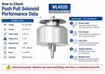
BUYER GUIDE - 5 KEY PARAMETERS Stroke Length Determines movement distance, must match application requirement Check starting force and holding force, ensure enough load capacity Important for continuous operation, prevent overheating problems Match system power supply, Response Time Important for high-speed automation, faster response improves efficiency Incorrect parameter selection may cause overheating, weak force, or shortened service life.
Open the catalog to page 5
* WL4020 Push Pull Magnetic Solenoid * Material Inspection • Check copper wire purity • Verify steel material hardness • Confirm dimensions Coil Winding Test • Automatic winding inspection • Resistance consistency checking Assembly Inspection • Precise component fitting • Stable plunger movement testing Performance Testing • Force testing • Voltage testing • Stroke verification Final Quality Check • Appearance inspection • Packaging verification • Shipping approval 100% Tested Before Shipment Precision Performance •m Quality
Open the catalog to page 6
Force Requirement y Required push or pull force? y Starting force or holding force? Need Custom Push Pull Solenoid Solutions?Contact Our Engineering Team Today Let’s Build the Right Solution for Your Application!
Open the catalog to page 7
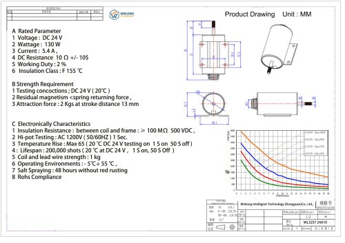
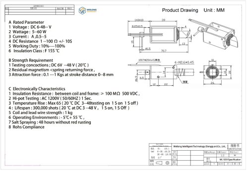
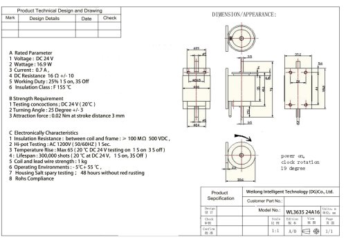
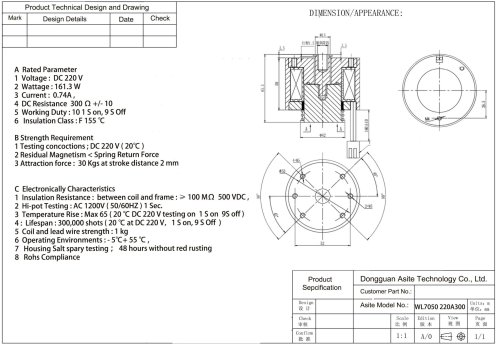
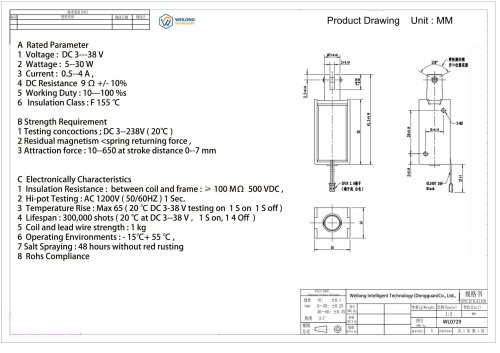
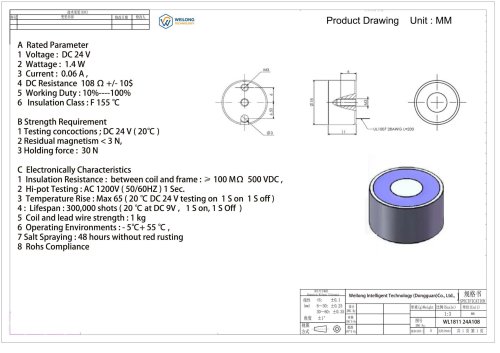
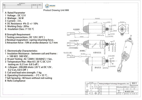
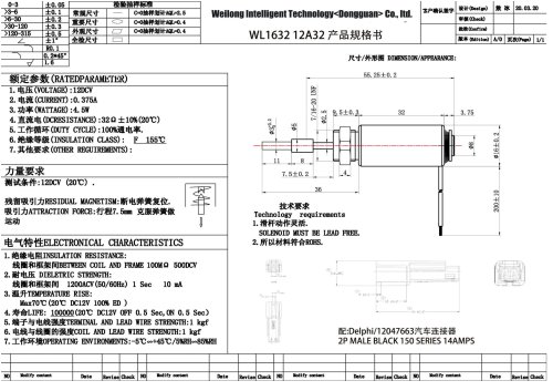
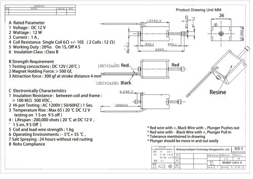
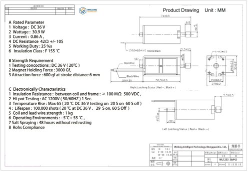
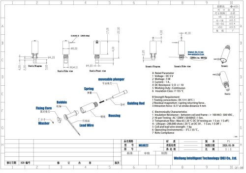
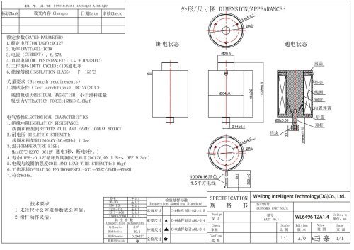
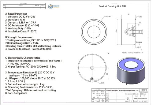
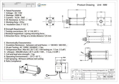
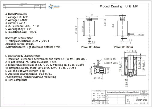
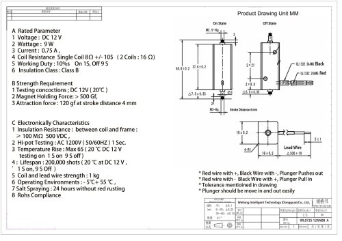
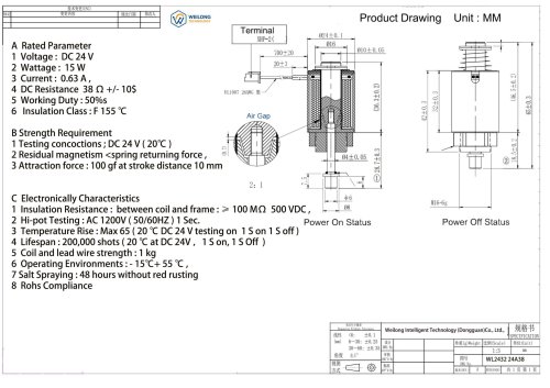
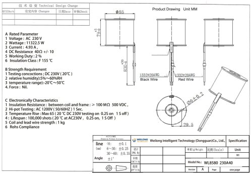
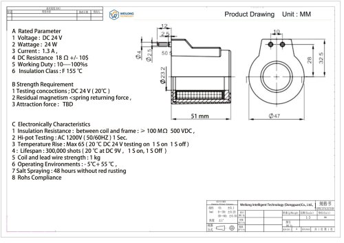
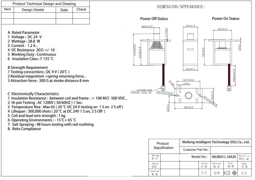
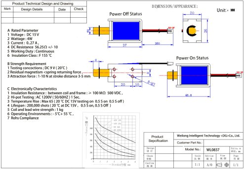
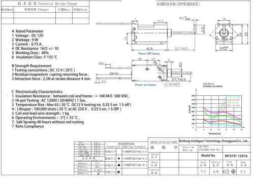
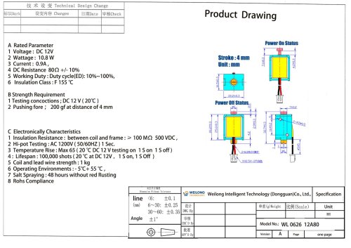
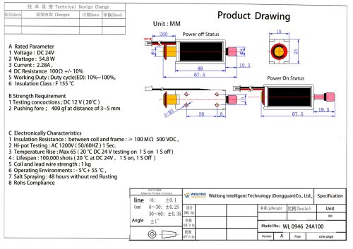
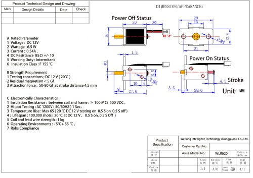
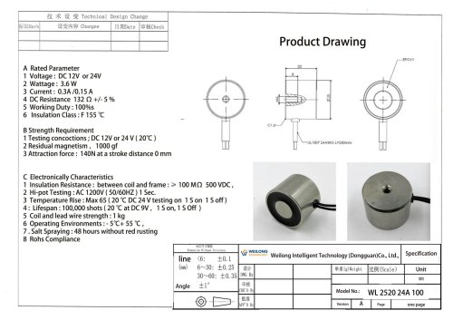
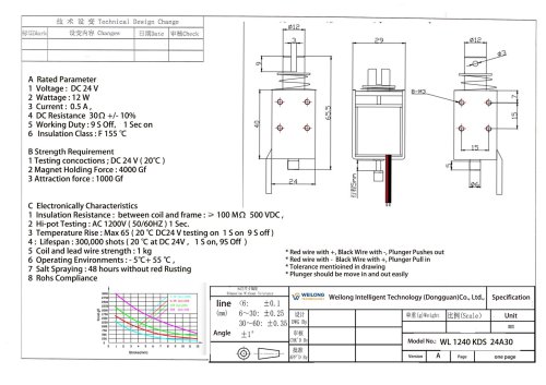
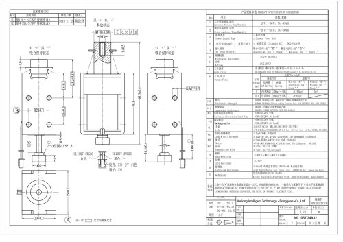
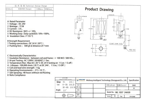
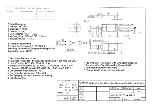
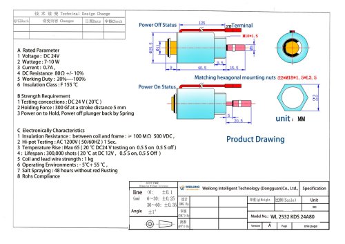
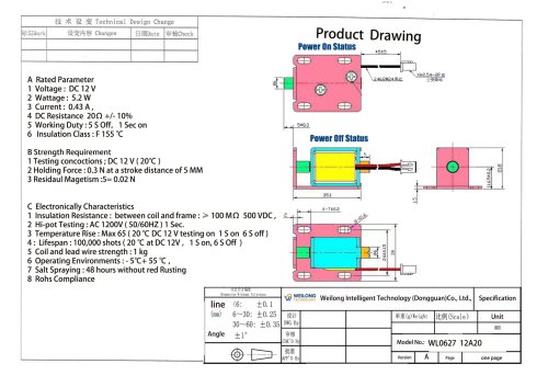
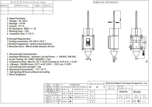
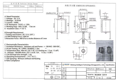
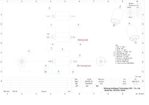
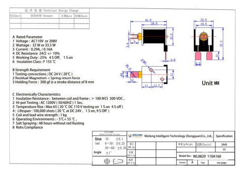
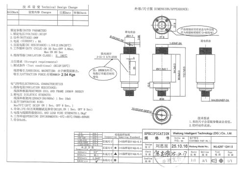
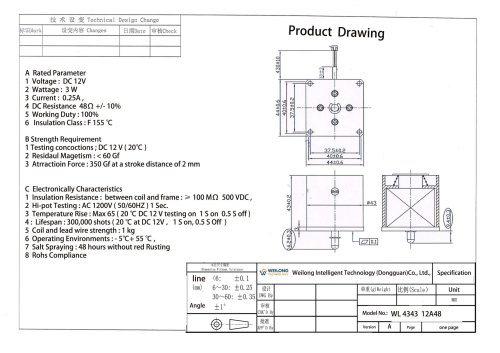
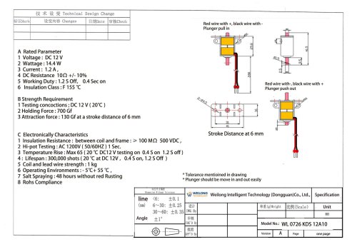
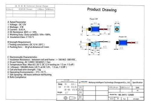
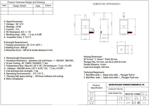
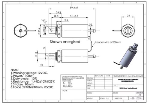
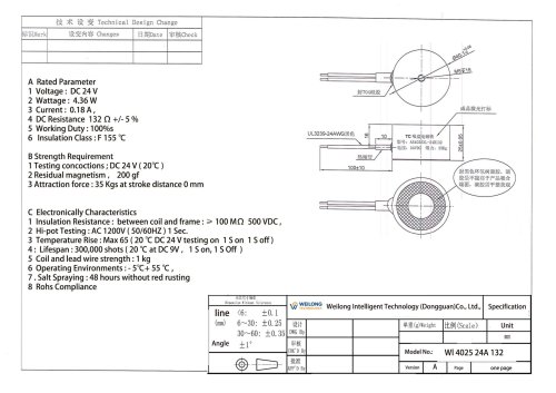
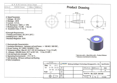
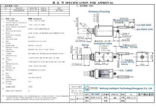
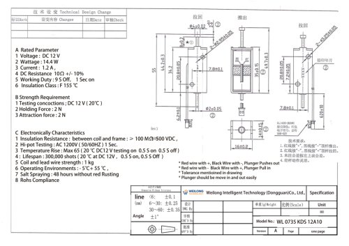
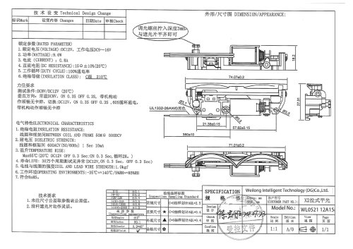
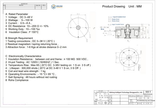
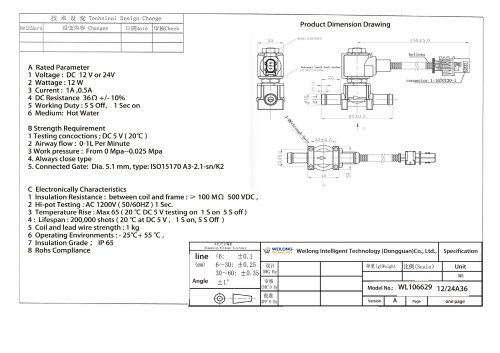
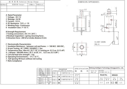
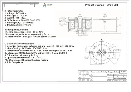
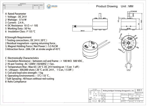
Product Technical Design and Drawing DIMENSION/APPEARANCE: A Rated Parameter 5 Working Duty: Continuous 2 Residual magnetism <spring returning force, 3 Attraction force: 300 G at stroke distance 8 mm 1 Insulation Resistance: between coil and frame :> 100 MO 500 VDC, 3 Temperature Rise: Max 65 (20 °C DC 24 V testing on 1 S on 2 S off) 5 Coil and lead wire strength : 1 kg 7 Salt Spraying : 48 hours testing with red rusthiing 8. Rohs Compliance
Open the catalog to page 8All Weilong Intelligent Technology (Dongguan) Co., Ltd. catalogs and technical brochures
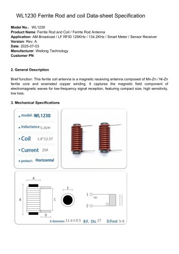 WL1230 Rod Core Ferrite Coil
3 Pages
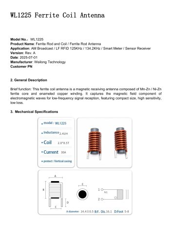 WL1225 Ferrite Coil Antenna
3 Pages
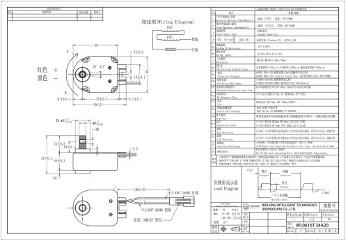 WL0616 Holding Solenoid
8 Pages
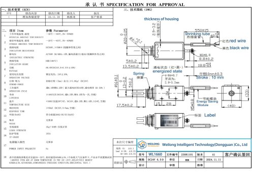 WL3031 Holding electromagnet
8 Pages
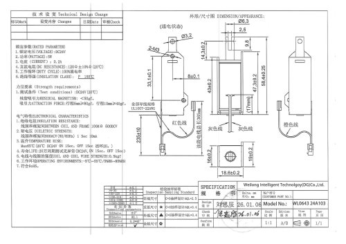 WL 0643 Pull Solenoid
7 Pages
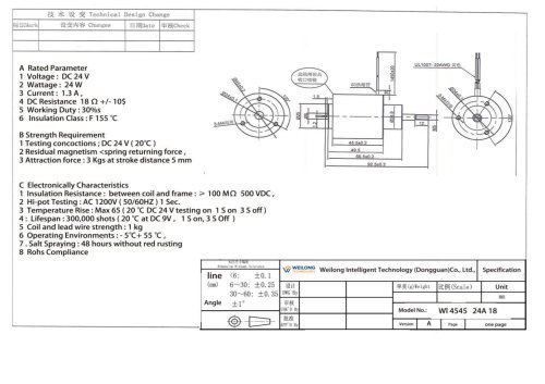 WL4545 push pull solenoid DC
8 Pages