- Catalogs
- Weilong Intelligent Technology (Dongguan) Co., Ltd.
- WL1535 Industrial Coil Bobbin Solutions


- Company
- Products
- Catalogs
- News & Trends
- Exhibitions
WL1535 Industrial Coil Bobbin Solutions
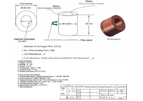
WL1535 Industrial Coil Bobbin Solutions
Coil bobbins offer significant benefits in industrial applications. They provide excellent insulation between windings and cores, which reduces the risk of electrical failures. The precise structure of bobbins ensures uniform winding distribution, enhancing electromagnetic efficiency. Made from engineering plastic materials, they offer heat resistance, flame retardancy, and mechanical strength. Bobbins facilitate mass production through automated winding processes, improve product durability, and minimize vibration-related damage. Custom designs allow for the integration of terminals and mounting structures, which reduces assembly time.
Despite their advantages, plastic bobbins can deform under extreme temperatures if inappropriate materials are used. In high-power applications, additional insulation systems may be necessary. Poor design can lead to limited heat dissipation. Compared to direct winding methods, bobbins can slightly increase material costs and component size. Improper dimensional tolerances can negatively impact coil performance.
Overall, when properly designed and with the right material selection, the benefits of using coil bobbins outweigh the limitations.
Catalog excerpts
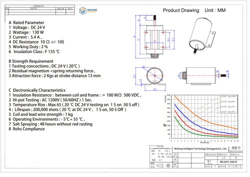
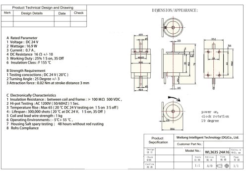
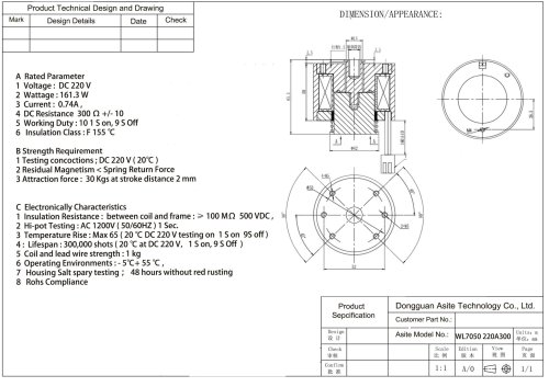
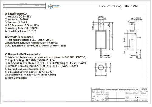
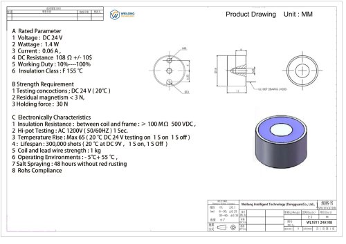
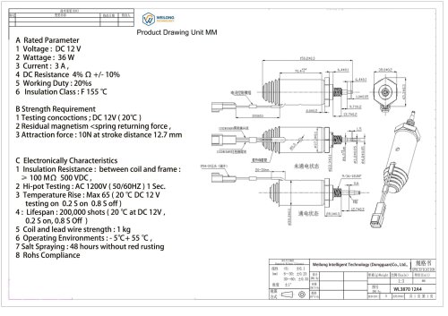
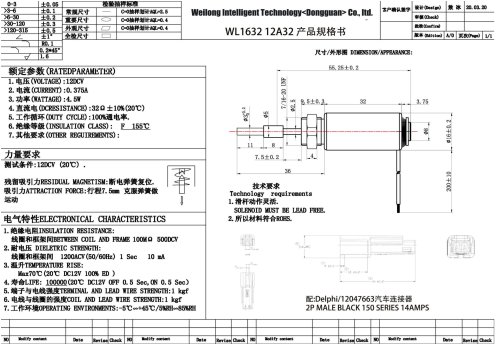
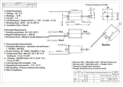
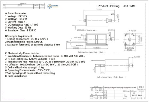
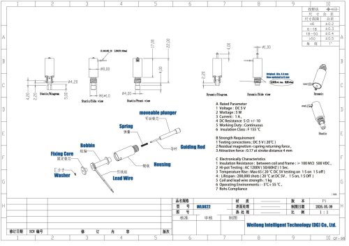
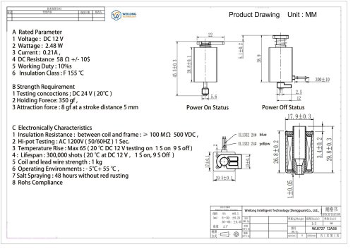
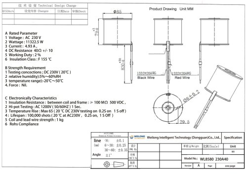
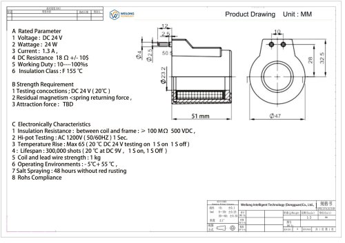
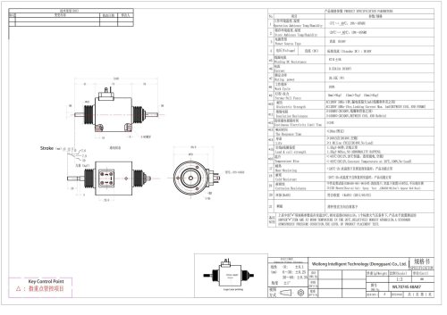
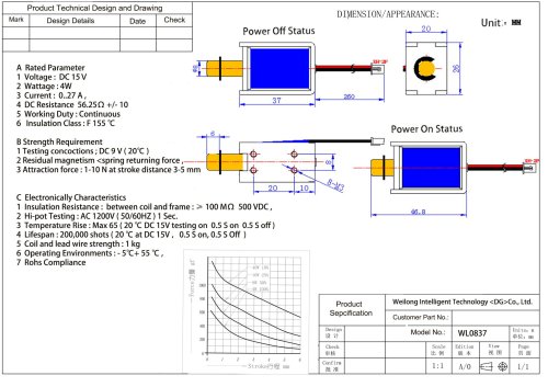
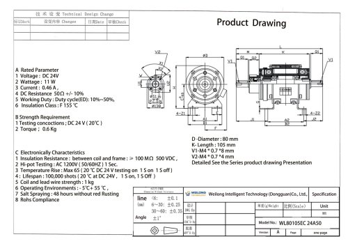
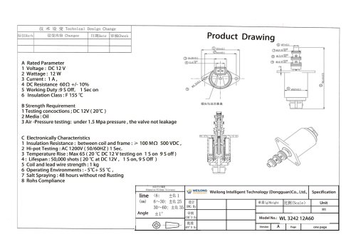
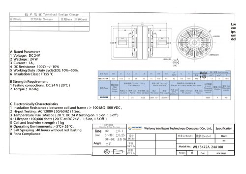
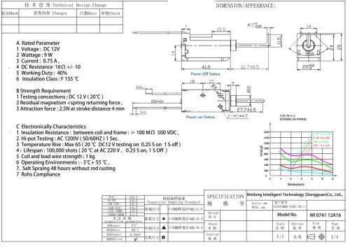
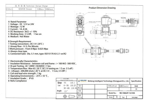
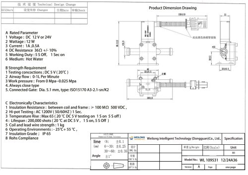
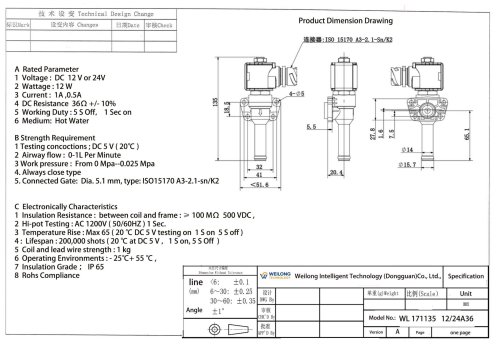
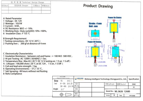
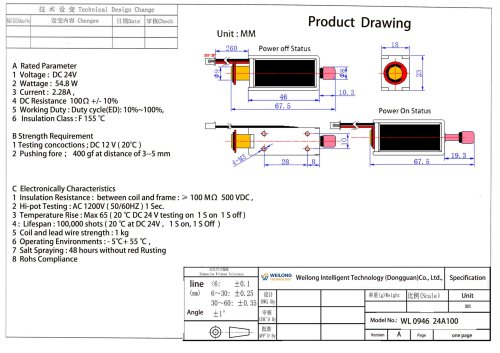
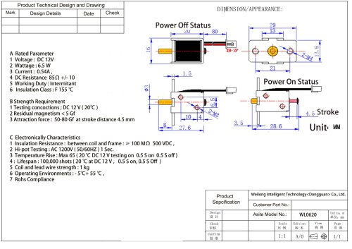
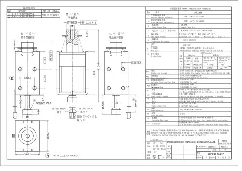
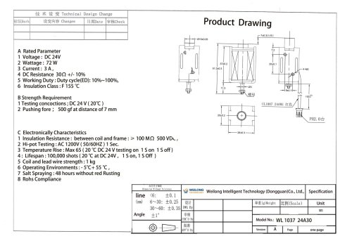
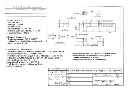
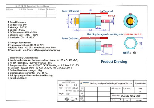
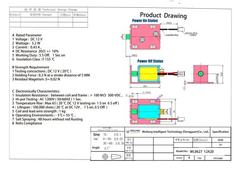
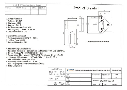
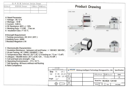
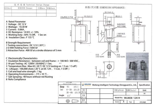
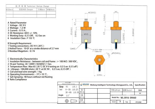
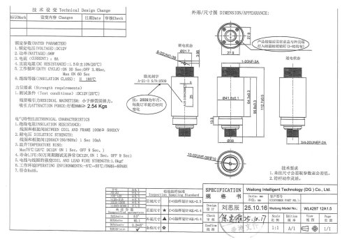
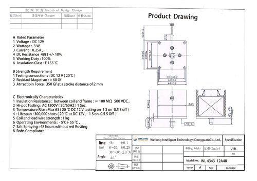
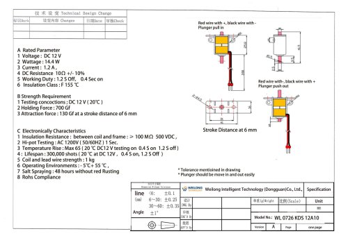
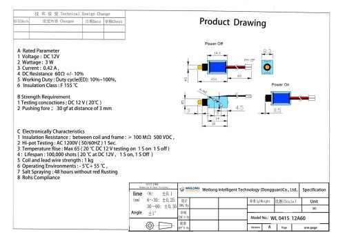
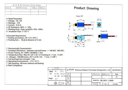
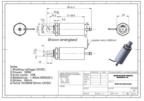
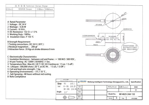
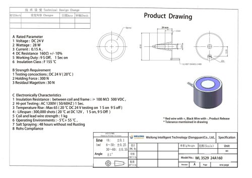
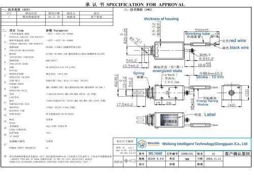
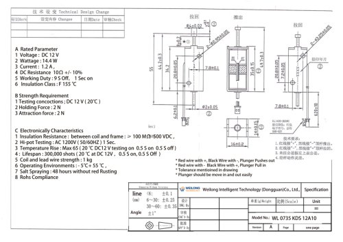
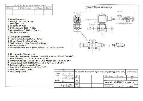
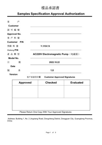
4. Coil inductance (Under what test est conoitions? Test frequency?) ...X 1 Insulation Resistance: between coil and frame :> 100 MO SOOVDC, 3 Temperature Rise: Max6S( 20"C DC 12 V testing on 1 S on 95 off) 5 Coil and lead wire strength: 1 kg
Open the catalog to page 1
WL1535 Industrial Coil Bobbin Solutions Advantages: Coil bobbins provide excellent insulation between windings and cores, reducing electrical failure risks. Their precise structure ensures uniform winding distribution, improving electromagnetic efficiency. Engineering plastic materials offer heat resistance, flame retardancy, and mechanical strength. Bobbins simplify mass production through automated winding processes. They also enhance product durability and reduce vibration-related damage. Custom designs allow integration of terminals and mounting structures, reducing assembly time. Disadvantages:...
Open the catalog to page 2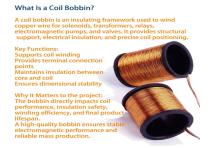
A coil bobbin is an insulating framework used to wind copper wire for solenoids, transformers, relays, electromagnetic pumps, and valves. It provides structural support, electrical insulation, and precise coil positioning Supports coil winding Provides terminal connection points Maintains insulation between core and coil Ensures dimensional stability The bobbin directly impacts coil performance, insulation safety, winding efficiency, and final product lifespan. « A high-quality bobbin ensures stable electromagnetic performance and reliable mass production.
Open the catalog to page 3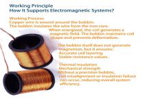
Working Process: Copper wire is wound around the bobbin. The bobbin insulates the wire from the iron core. When energized, the coil generates a magnetic field. The bobbin maintains coil shape and prevents deformation. The bobbin itself does not generate Accurate coil layering Stable resistance values. Thermal insulation Mechanical strength Without a precision bobbin, coil misalignment or insulation failure can occur, reducing overall system efficiency.
Open the catalog to page 4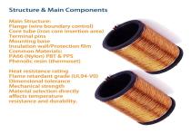
Structure & Main Components Main Structure: Flange (wire boundary control) Core tube (iron core insertion area) Terminal pins Mounting base Insulation wall/Protection film Common Materials: PA66 (Nylon) PBT & PPS Phenolic resin (thermoset) Heat resistance rating Flame retardant grade (UL94-V0) Dimensional tolerance Mechanical strength Material selection directly affects temperature resistance and durability.
Open the catalog to page 5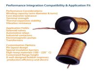
Performance Considerations: Winding capacity (wire diameter & turns) Core diameter tolerance Terminal strength Thermal expansion stability Vibration resistance Application Fields: Solenoid valves Automotive relays Industrial contactors Electromagnetic pumps Transformers Customization Options: Pin layout design Special insulation barriers High-temp materials (180 - 220° C) Customized flange height A well-designed bobbin improves production efficiency and electro
Open the catalog to page 6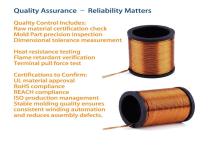
Quality Control Includes: Raw material certification check Mold Part precision inspection Dimensional tolerance measurement Heat resistance testing Flame retardant verification Terminal pull force test UL material approval RoHS compliance REACH compliance ISO production management Stable molding quality ensures consistent winding automation and reduces assembly defects.
Open the catalog to page 7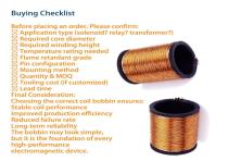
Before placing an order. Please confirm: S3 Application type (solenoid? relay? transformer?) S3 Required core diameter Required winding height Temperature rating needed S3 Flame retardant grade Pin configuration Mounting method Quantity & MOQ S3 Tooling cost (if customized) S3 Lead time Final Consideration: Choosing the correct coil bobbin ensures: Stable coil performance Improved production efficiency Reduced failure rate Long-term reliability The bobbin may look simple, but it is the foundation of every high-performance electromagnetic device.
Open the catalog to page 8All Weilong Intelligent Technology (Dongguan) Co., Ltd. catalogs and technical brochures
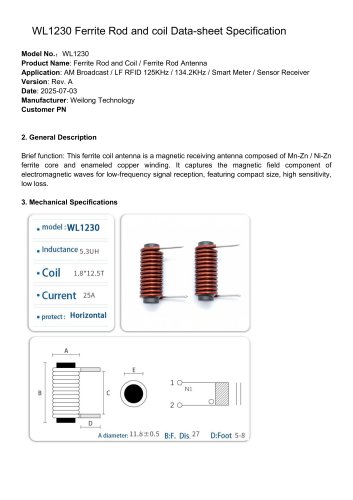 WL1230 Rod Core Ferrite Coil
3 Pages
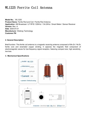 WL1225 Ferrite Coil Antenna
3 Pages
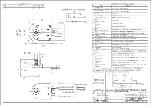 WL0616 Holding Solenoid
8 Pages
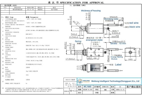 WL3031 Holding electromagnet
8 Pages
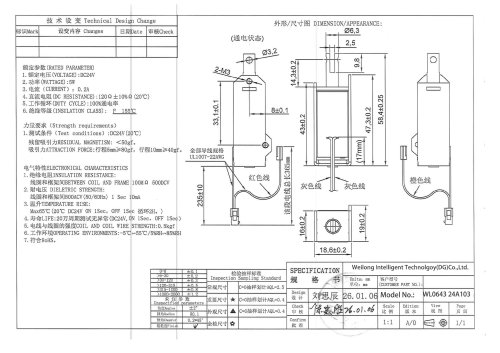 WL 0643 Pull Solenoid
7 Pages
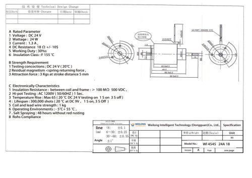 WL4545 push pull solenoid DC
8 Pages