Group: WEG

Catalog excerpts

Safety in every movement Motors | Automation | Energy | Transmission & Distribution | Coatings
Open the catalog to page 1
Switch-Disconnectors MSWSummary Introduction General Characteristics Selection Change-Over Switch Switch-Disconnectors in Thermoplastic Enclosure Switch-Disconnectors Accessories Dimensions
Open the catalog to page 3
EVERY MOVEMENT MSW switch-disconnectors were developed according to IEC 60947-3 / UL 508 and enable the manual drive of motors, machines and other equipment. They are also used to drive and interrupt electrical circuits under load conditions. Modern and compact design, demanding little installation space IP65 protection rating handles that allow the use of up to three padlocks and door interlocking Complete accessory line ON/OFF indication on the handle Terminals with IP20 degree of protection Two mounting options for the switch-disconnectors, meeting the needs of different applications
Open the catalog to page 4
Mounting on base Switch-disconnector in IP65 enclosure Mounting on base - direct command switch Mounting on base change-over switch
Open the catalog to page 5
Note: auxiliary contacts are not available for MSW 12, MSW 16, MSW 20 and MSW 100 switch-disconnectors
Open the catalog to page 6
HOW TO SELECT THE MSW ACCORDING TO YOUR APPLICATION? Current Mounting The MSW line offers a range of accessories and configurations, available in the default configuration and which can be selected to suit the application requirements. Check out below the four steps necessary for the proper selection of the MSW switch-disconnector. 1 - Mounting MSW switch-disconnectors are mounted on panel doors or bases according to the selected model. g Mounting on door: in this system, the switch-disconnector is mounted on panel doors by means of screws. The switchdisconnector and the handle are always...
Open the catalog to page 8
Accessories Handle 4 - Accessories 4.a - Auxiliary Contacts The MSW line provides auxiliary contacts for mounting on the sides of the switch-disconnector. On each side of the switch-disconnector, it is possible to mount an auxiliary contact, as shown in the figure on the right. 4.b - Terminal Cover In compliance with the Brazilian regulatory standard NR10, the MSW line offers terminal covers for protection against inadvertent touches, reducing the risk of direct contact with the switch-disconnector terminals. 4.c - Additional Pole For applications that require disconnection of the neutral,...
Open the catalog to page 9
Change-Over Switch Both power supplies 1 and 2 are OFF Disconnection of power supply 1 Disconnection of power supply 2 It is possible to lock with up to 3 padlocks 1 Interruption on the 4 poles by installing the additional pole The reversing switch consists of two on-load switch-disconnectors. The interlocking prevents both power supplies from being simultaneously turned on, ensuring complete separation between the electrical circuits. When the handle is placed in number 1, the power supply on the left is disconnected. When the handle is placed in number 2, the power supply on the right is...
Open the catalog to page 10
Change-Over Switch 3-pole terminal cover 1-pole terminal cover Additional pole Note: 1) The fitting of the auxiliary contact on the additional pole (as shown in the picture) is only possible on 125 and 160 A models. Other models must be fitted directly to the switch-disconnector.
Open the catalog to page 11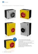
Surface-mounted switch-disconnectors (base); ■ Four current options: 25 A, 40 A, 63 A and 80 A; ■ Two color options: yellow cover with red handle or gray cover with black handle; ■ Locking in the OFF position with up to three padlocks; ■ Knock-outs for cable gland: flexibility allowing cable entry/exit at the top, bottom and rear of the box; ■ Robust and heat resistant enclosures; ■ An additional pole can be installed (accessory item); ■ An auxiliary contact can be installed (accessory item); ■ IP65 protection rating.
Open the catalog to page 12
Switch-DisconnectorsMounting on Top Reference code Notes: 1) The standard supply includes rotary handle for the panel door in red and escutcheon in yellow. 2) Only the mechanism of the switch-disconnector is supplied (no rotary handle). 3) Supply of the switch-disconnector with black handle on request. Notes: 1) Red rotary handle for panel door and yellow escutcheon included. 2) Only the mechanism of the switch-disconnector is supplied (no rotary handle and no shaft). 3) Supply of the switch-disconnector with black handle on request.
Open the catalog to page 13
Mounting on Base - Direct Command Switch Reference code Note: black rotary handle. Change-Over Switch Reference code Reference code Note: black enclosure base.
Open the catalog to page 14
Accessories Rotary Operating Handle ■ Prevents the panel door from being opened while the switch-disconnector is in the ON position (valid for base-mounted switch-disconnectors); ■ Total locking (switch-disconnector + panel door) in the OFF position with up to three padlocks; ■ IP65 protection rating; ■ Base-mounted switch-disconnector models come with standard shaft. Notes: 1) The same item can be installed on either side of the switch-disconnector. 2) Auxiliary contact block can be assembled.
Open the catalog to page 15
Accessories Auxiliary Contact ■ Direct mounting on the side of the switch-disconnector; ■ It is possible to install up to two auxiliary contacts per switch-disconnector; ■ Models for base-mounted switches: application in MSW (base), MSWD, MSWR and MSWB; ■ Models for top-mounted switches (door): application in MSW (top). Note: 1) Fastening the auxiliary contact to the additional pole accessory item is only possible in 125 A and 160 A models. Other models must be fastened directly to the switch-disconnector. Terminal Cover ■ Provides protection against inadvertent touch on the...
Open the catalog to page 16
MANUAL DE INSTALAÇÃO ILLUSTRATIVO DI INSTRUCTION MANUAL MONTAGGIO MANUAL DE INSTALACIÓN OPERATING SERIE MSW12 – MSW16 – MSW20 INSTRUCTION Dimensions Montagem em Painel / Panel mounting / Ensamble em Tablero SERIE MSW63 – MSW 12 P2 / MSW 16 P2 / MSW 20 P2 es/polos: MSW80 SW 12 P-3 Los valores demostrados pueden ser cambiados sin aviso previo. La información és de referencia solamente. Painel Panel Tablero MANUAL DE INSTALAÇÃO ILLUSTRATIVO DI INSTRUCTION MANUAL MONTAGGIO MANUAL DE INSTALACIÓN OPERATING polos: SERIE MSW12 – MSW16 – MSW20 12 P-2 INSTRUCTION Montagem em Painel / Panel mounting /...
Open the catalog to page 17All WEG catalogs and technical brochures
-
 MTW
MTW24 Pages
-
 MOTION FLEET MANAGEMENT
16 Pages
-
 CFW100 - VARIABLE SPEED DRIVE
16 Pages
-
 ELECTRIC MOTORS
68 Pages
-
 CFW10 Variable Speed Drive
8 Pages
-
 Enclosed Starters
16 Pages
-
 AG10 Line
52 Pages
-
 W22Xdb Flameproof Motors
23 Pages
-
 Low Voltage Motor Control Center
12 Pages
-
 CFW500 - VARIABLE SPEED DRIVE
32 Pages
-
 Pump Genius
16 Pages
-
 RW - THERMAL OVERLOAD RELAYS
28 Pages
-
 CONTACTORS - CWM LINE
52 Pages
-
 TURBOGENERATORS
8 Pages
-
 CWB Contactors
4 Pages
-
 CWB - CONTACTORS
48 Pages
-
 COMPACT CONTACTORS CWC0
36 Pages
-
 W22 Top Premium IE3
5 Pages
-
 SOFT-STARTERS
28 Pages
-
 SRW01 - SMART RELAY
28 Pages
-
 Product Portfolio
16 Pages
-
 WEG MANUFACTURING SITES
16 Pages
-
 Energy Applications Book
32 Pages
-
 SSW900 - SOFT-STARTER
20 Pages
-
 CFW300 Variable Speed Drive
16 Pages
-
 Geared Motors - Technical Catalogue
584 Pages
-
 Drives & Controls
20 Pages
-
 Solutions for Oil & Gas Industry
24 Pages
-
 Energy - Products and Solutions
24 Pages
-
 Solutions for Marine Indrustry
20 Pages
-
 Low Voltage Switch & Control Gear
242 Pages
-
 MSW - Switch Disconnectors
20 Pages
-
 Smoke Extraction
4 Pages
-
 Synchronous Alternators
12 Pages
-
 DC Motors
8 Pages
-
 ABW Air Circuit Breaker
40 Pages
-
 CFW700
4 Pages
-
 CFW500 Machinery Drives - VSD
16 Pages
-
 This is WEG
8 Pages
-
 WEG Around the World
8 Pages
-
 Water Cooled Motor
8 Pages
-
 Hydrogenerator
16 Pages
-
 FSW - Fuse Switch Disconnectors
12 Pages
-
 D and NH Fuses
8 Pages
-
 DW Molded-case Circuit Breaker
36 Pages
-
 DC Motor
8 Pages
-
 Motors - Product Lines
24 Pages
-
 WEG Motors Success Cases
60 Pages


Archived catalogs
-
 DC motor
20 Pages
-
 Fuse
Fuse3 Pages
-
 Explosion Proof Motor
64 Pages
-
 Electric transformer
8 Pages
-
 Contactor
84 Pages
-
 Frequency inverter
2 Pages
-
 Timer
Timer8 Pages
-
 Electric generator
8 Pages
-
 High Voltage Motor
20 Pages
-
 Cast Iron MV Motor
20 Pages
-
 Smoke Application
38 Pages
-
 Appliance Motors
33 Pages
-
 Electronic Softstarter
2 Pages
-
 Asynchronous motor
12 Pages
-
 Brake Motor
14 Pages


