Group: WEG

Catalog excerpts
SPECIFICATION GUIDE ELECTRIC MOTORS Motors | Automation | Energy | Transmission & Distribution | Coatings
Open the catalog to page 1
Specification of Electric Motors WEG, which began in 1961 as a small factory of electric motors, has become a leading global supplier of electronic products for different segments. The search for excellence has resulted in the diversification of the business, adding to the electric motors products which provide from power generation to more efficient means of use. This diversification has been a solid foundation for the growth of the company which, for offering more complete solutions, currently serves its customers in a dedicated manner. Even after more than 50 years of history and...
Open the catalog to page 3
Specification of Electric Motors
Open the catalog to page 4
Specification of Electric Motors
Open the catalog to page 5
1. Fundamental Concepts 1.1 Electric Motors The electric motor is a machine capable of converting electrical energy into mechanical energy. The induction motor is the most widely used type of motor because it combines all the advantages offered by the electrical energy such as low cost, easy of supply and distribution, clean handling and simple controls - together with those of simple construction and its great versatility to be adapted to wide ranges of loads and improved efficiencies. The most common types of electric motors are: a ) Direct current motors These motors are quite expensive...
Open the catalog to page 6
1.2 Basic Concepts For a better understanding of the next sections, the following are described the concepts of some principles of Physics concerning energy and forces. 1.2.1 Torque Torque, also known as moment of force, is the measure of the energy required to rotate a shaft. Through practical experience, we can note that for lifting a weight similar to the one used in water wells (see figure 1.2). The required force “F” to be applied on the winch depends on the length “E” of the crank handle. The larger the crank handle, the less force is required. By doubling the length “E” of the crank...
Open the catalog to page 7
DC Circuits The “electric power” on DC circuits can be obtained by the ratio among voltage (U), current (I) and resistance (R) involved in such circuit, that is: P 1.2.4 Apparent, Active and Reactive Power Apparent power ( S ) It is the multiplication result of the voltage by the current ( S = U . I for single-phase systems and S =√ 3 . U . I, for three-phase systems. This corresponds to the effective power which exists when there is no phase displacement of the current, i. e. for the resistive loads. Then, Where: U = voltage ( V ) I = current ( Amps ) R = resistance ( Ω ) P = average Power...
Open the catalog to page 8
1.2.5 Power Factor The power factor is indicated by cos ϕ, where ϕ is the angle of voltage displacement relating to the current. It is the relationship between active ( P ) and the apparent power ( S ) (Figure 1.3). P cos ϕ Then we can state that, g Resistive load: cos ϕ = 1 g Inductive load: cos ϕ ( delayed ) g Capacitive load: cos ϕ ( advanced ) Note: he terms “delayed” and “advanced” refers to the current angle relating t to the voltage angle. A motor does not draw only active power, transformed after in mechanical power and heat (losses), but also absorbs reactive power needed for...
Open the catalog to page 9
Original Power Factor Required Power Factor 0,83 Table 1.2 - Power factor correction Specification of Electric Motors
Open the catalog to page 10
1.2.6 Efficiency The electric motor efficiency is defined as how efficient it is to make the conversion of the line absorbed electric energy into mechanical energy available at the shaft end. The efficiency defines how this transformation is made. By calling mechanical power available at the shaft end “output” (Pu ) and electric energy absorbed by the motor from the supply “input” (Pa ), the efficiency is the ratio between these two, i.e., η= By representing the values U and I in a graph at successive instants, we obtain figure 1.5b. Figure 1.5b also shows some values which will be defined...
Open the catalog to page 11
Two equal loads can be connected, for example, to a singlephase system, in two different ways: g By making a series connection ( figure 1.6a ), where the total current flows through the two loads. In this case, the voltage across each load is half of the circuit voltage. g y making a parallel connection ( figure 1.6b ), where the B voltage is applied across each load. In this case, the current in each load is half of the total circuit current. 1.4 Three-Phase AC System A three-phase system is formed by associating three singlephase voltage system, U1, U2 and U3 which so the phase...
Open the catalog to page 12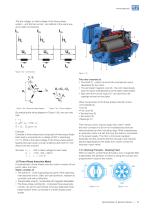
The line voltage, or rated voltage of the three-phase system - and the line current - are defined in the same way as for delta-connections. Figure 1.9b - Electrical wiring diagram Figure 1.9c - Phasor diagram By analyzing the wiring diagram in Figure 1.9b, one can note that: U = Uf1 - Uf2 (figure 1.9c) Example: Consider a three-phase load composed of three equal loads. Each load is connected to a voltage of 220 V, absorbing 5.77 A. What is the rated voltage of the three-phase system feeding this load under normal conditions (220 and 5.77 A)? What is the line current? We have Uf = U = I =...
Open the catalog to page 13
a ) igure 1.11a shows a single-phase winding through F which flow the current I, and the field H, generated by the current. The winding is composed of one pair of poles, the North Pole and the South Pole, the effects of which are added to produce field H. The magnetic flux passes through the rotor, across both poles and links up with itself by means of the stator core. When "I" is an alternating current, field H is established in the same way, so that its value is represented at every instant, by the same chart shown in figure 1.5b, also reversing its direction at every half cycle. The...
Open the catalog to page 14
1.5.3 Slip ( s ) If the motor runs at a speed different from the synchronous speed, i.e. differing from the speed of the rotating field, the rotor winding “cut” the magnetic force lines of the field and so, according to the electromagnetism laws, induced currents will flow through the rotor winding. The heavier the load the higher must be the required torque to move it. To obtain a higher torque, the speed difference must be greater so that induced current and the generated field becomes higher. Therefore, as the load increases, the motor speed decreases. When the load is at zero (motor at...
Open the catalog to page 15All WEG catalogs and technical brochures
-
 MTW
MTW24 Pages
-
 MOTION FLEET MANAGEMENT
16 Pages
-
 CFW100 - VARIABLE SPEED DRIVE
16 Pages
-
 CFW10 Variable Speed Drive
8 Pages
-
 Enclosed Starters
16 Pages
-
 AG10 Line
52 Pages
-
 W22Xdb Flameproof Motors
23 Pages
-
 Low Voltage Motor Control Center
12 Pages
-
 CFW500 - VARIABLE SPEED DRIVE
32 Pages
-
 Pump Genius
16 Pages
-
 RW - THERMAL OVERLOAD RELAYS
28 Pages
-
 CONTACTORS - CWM LINE
52 Pages
-
 TURBOGENERATORS
8 Pages
-
 CWB Contactors
4 Pages
-
 CWB - CONTACTORS
48 Pages
-
 COMPACT CONTACTORS CWC0
36 Pages
-
 W22 Top Premium IE3
5 Pages
-
 SOFT-STARTERS
28 Pages
-
 SRW01 - SMART RELAY
28 Pages
-
 MSW - SWITCH-DISCONNECTORS
36 Pages
-
 Product Portfolio
16 Pages
-
 WEG MANUFACTURING SITES
16 Pages
-
 Energy Applications Book
32 Pages
-
 SSW900 - SOFT-STARTER
20 Pages
-
 CFW300 Variable Speed Drive
16 Pages
-
 Geared Motors - Technical Catalogue
584 Pages
-
 Drives & Controls
20 Pages
-
 Solutions for Oil & Gas Industry
24 Pages
-
 Energy - Products and Solutions
24 Pages
-
 Solutions for Marine Indrustry
20 Pages
-
 Low Voltage Switch & Control Gear
242 Pages
-
 MSW - Switch Disconnectors
20 Pages
-
 Smoke Extraction
4 Pages
-
 Synchronous Alternators
12 Pages
-
 DC Motors
8 Pages
-
 ABW Air Circuit Breaker
40 Pages
-
 CFW700
4 Pages
-
 CFW500 Machinery Drives - VSD
16 Pages
-
 This is WEG
8 Pages
-
 WEG Around the World
8 Pages
-
 Water Cooled Motor
8 Pages
-
 Hydrogenerator
16 Pages
-
 FSW - Fuse Switch Disconnectors
12 Pages
-
 D and NH Fuses
8 Pages
-
 DW Molded-case Circuit Breaker
36 Pages
-
 DC Motor
8 Pages
-
 Motors - Product Lines
24 Pages
-
 WEG Motors Success Cases
60 Pages


Archived catalogs
-
 DC motor
20 Pages
-
 Fuse
Fuse3 Pages
-
 Explosion Proof Motor
64 Pages
-
 Electric transformer
8 Pages
-
 Contactor
84 Pages
-
 Frequency inverter
2 Pages
-
 Timer
Timer8 Pages
-
 Electric generator
8 Pages
-
 High Voltage Motor
20 Pages
-
 Cast Iron MV Motor
20 Pages
-
 Smoke Application
38 Pages
-
 Appliance Motors
33 Pages
-
 Electronic Softstarter
2 Pages
-
 Asynchronous motor
12 Pages
-
 Brake Motor
14 Pages


