- Catalogs
- Wecon Technology Co.Ltd
- WECON PLC&MODULES technical features2014
- Products
- Catalogs
- News & Trends
- Exhibitions
WECON PLC&MODULES technical features2014
1 /36Pages

WECON PLC&MODULES technical features2014
1 /36Pages
Catalog excerpts

WECON PLC&MODULES TECHNICAL FEATURES 2014 Wecon Technology Co.Ltd., SITE: http://en.we-con.com.cn Techinical Support: [email protected] Skype: fcwkkj PHONE: 86-591-87868869
Open the catalog to page 1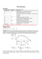
PTO Instruction Description The description of starting address S1, shown in following list. Address offset Stage Description 0 Number of stages:1~255 (No output when 0) Record stages number of current running Executions of envelope table (-1:Disable 0: infinite) (Restart to ake effect ) Initial frequency (Range; 0~200,000) Initial frequency (Range: 0~200,000) Note :The address is occupied double words when using DPTO instruction(32 bits),so the address offset is 2. Example program: Example:Using PTO with pulse envelope to control stepping motor, for simple speed up constant speed, speed down...
Open the catalog to page 3
According to the formula of frequency increment in Notes.4. The frequency increment in each stage: Stage 1 (Speed up) Frequency increment=40; Stage 2 (constant speed) Frequency increment=0; Stage 3 (Speed down) Frequency increment=-20; According to the instruction and Fig.1, got the following envelop table: Stage Total number of stages Record stages number of current running Executions of envelope 0:Infinite)(Restart to take effect) Initial frequency Frequency increment Initial frequency Frequency increment Initial frequency Frequency increment Notes: 1. Based on frequency, start instruction...
Open the catalog to page 4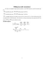
PWM(pulse width modulation) The relay is not suitable for high frequency operation, so the PWM instruction is used for transistor type is specified pulse width, is specified pulse cycle, dE)<CHI^,Setting range 1~32,767ms; is specified output port, as LX2N you can use Y0~Y3, and use Y0~Y1 in LX1S. And the port can't be occupied by PLSY or PLSR instruction. This instruction is running as interrupt type, stop output when OFF, the value of and dl^can be modified at runtime. Example program: Width Cycle
Open the catalog to page 5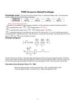
PWM Panasonic Mode(Permillage) Permillage mode: The cycle time will be divided 1000, it is called permillage mode. The relationship between output bit and control shown as following: Stay in normal mode when OFF. The relay is not suitable for high frequency operation, so this instruction is used for transistor type PLC. is specified duty cycle, is specified pulse output cycle, is specified output port, as LX2N you can use Y0~Y3, and use Y0~Y1 in LX1S. And the port can’t be occupied by PLSY or PLSR instruction. This instruction is running as interrupt type, stop output when OFF, the value of Example...
Open the catalog to page 6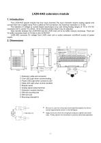
The LX2N-4AD special module has four input channels.The input channels receive analog signals and convert them into a digital value.This is called an A/D conversion, the maximum resolution is 12 bits. The selection of voltage or current based input/output is by user wiring.Analog ranges of -10 to 10V DC Data transfer between the LX2N-4AD and the LX2N main unit is by buffer memory exchange. There are 32 buffer memories (each of 16 bits) in the LX2N-4AD. LX2N-4AD consume 5V voltage from LX2N main unit or active extension unit,90mA current of power © Extension cable and connector © Com LED:Light...
Open the catalog to page 7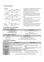
The analog input is received through a twisted pair shielded cable. This cable should be wired separately from power lines or any other lines which may induce electrical noise. If a voltage ripple occurs during input, or there is electrically induced noise on the external wiring, connect a smoothing capacitor of 0.1 to 0.47uF, If you are using current input, connect the V+ and l+ terminals to each other. If there is excessive electrical noise, connect the FG frame ground terminal with the grounded Connect the ground terminal on the LX2N-4AD unit with the grounded terminal on the main unit. Use...
Open the catalog to page 8
Analog Inputs continued. Current input Current input Preset ranges are selected by an appropriate setting in buffer memory of the analog block. Current/Voltage input selection must match the correct input terminal connections.
Open the catalog to page 9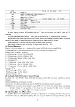
b7 b6 b5 b4 b3 b2 b1 b0 Reserved Reset to Defaults and Preset. Default = 0 Offset, Gain Adjust Prohibit. Default = (0, 1) Permit Offset, Gain Adjust G4 O4 G3 O3 G2 O2 G1 O1 Offset Value Default = 0 Gain Value Default = 5,000 Reserved Error status Identification code K2010 Cannot be used In buffer memory locations (BFMs)marked with an “*” data can be written from the PC using the TO command. For buffer memories (BFMs) without “*”mark, data can be read to the PC using the FROM command. Before reading from the analog special function block, ensure these settings have been sent to the analog special...
Open the catalog to page 10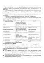
offset adjustments. (b) If (b1, b0) of BFM #21 is set to (1,0), gain and offset adjustments are prohibited to prevent inadvertent changes by the operator. In order to adjust the gain and offset values, bits (b1, b0) must be set to (0,1). The default is(0,1). (c) Gain and offset values of BFM #23 and #24 are sent to non-volatile memory gain and offset registers of the specified input channels. Input channels to be adjusted are specified by the appropriate G-O (gain-offset) bits of BFM #22. Example:If bits G1 and O1 are set to 1,input channel 1 will be adjusted when BFM #22 is written to by a TO...
Open the catalog to page 11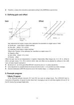
Therefore, a delay timer should be used before writing to the EEPROM a second time. 5. Defining gain and offset Gain determines the angle or slope of the calibration line,identified at a digital value of 1000. (a) Small gain Large steps in digital readings (b) Zero gain default : 5V or 20mA. (c) Large gain Small steps in digital readings. Offset is the ‘Position’ of the calibrated line, identified at a digital value of 0. (d) Negative offset. (e) Zero offset default : 0V or 4mA. (f) Positive offset. Offset and gain can be set independently or together. Reasonable offset ranges are -5 to +5V or...
Open the catalog to page 12
error value is normal The ID code for the special function block at position "0" is read from BFM #30 of that block and stored at D4 in the main unit. This is compared to check the block is a LX2N-4AD, if OK M1 is turned ON. These two program steps are not strictly needed to perform an analog read. They are however a useful check and are recommended as good practice. The analog input channels (CH1, CH2) are setup by The number of averaged samples for CH1 and CH2 is The operational status of the LX2N-4AD is read from BFM #29 and output as bit devices at the LX2N main If there are no errors in...
Open the catalog to page 13All Wecon Technology Co.Ltd catalogs and technical brochures
 PRODUCTS CATALOG
24 Pages
 Servo Catalog
8 Pages
 WECON Inverter
4 Pages
 NDUSTRX APPL CAT ON MANUAL
6 Pages
 LX3VP
LX3VP4 Pages
 Wecon A8 Products Catalog
6 Pages
 WECON PLC Products Catalog
8 Pages
 LX3V-4PT Module
8 Pages
 LX3V-4DA Module
9 Pages
 LX3V-4AD Module
9 Pages
 WECON LEVI777E catalog
3 Pages
 WECON PLC Catalog
8 Pages
 Wecon Tablet PC
9 Pages
 Wecon Products
10 Pages
 Wecon Industrial Panel PC
23 Pages
 WECON PLC Module LX2N-4AD
9 Pages
 WECON HMI Install Manual
2 Pages
 Wecon LX series PLC
8 Pages
 Wecon CNS7-200 serise PLC
34 Pages


