- Catalogs
- Wecon Technology Co.Ltd
- LX3V-4DA Module
- Products
- Catalogs
- News & Trends
- Exhibitions
LX3V-4DA Module
1 /9Pages

LX3V-4DA Module
1 /9Pages
Catalog excerpts
Wecon Technology Co.,Ltd. SITE: http://www.we-con.com.cn/en/ Technical Support: [email protected] Skype: fcwkkj PHONE: 86-591-87868869
Open the catalog to page 1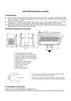
• The LX3V-4DA analog special function block has four output channels. The output channels take a digital value and output an equivalent analog signal. This is called a D/A conversion. The LX3V-4DA has • The selection of voltage or current based input/output is by user wiring. Analog ranges of -10 to 10V DC (resolution:5mV), orO to 20mA (resolution: 20uA) maybe selected independently for each channel. • Data transfer between the LX3V-4DA and the LX3V main unit is by buffer memory exchange. There are 32 buffer memories (each of 16 bits) in the LX3V-4DA. © Extension cable and connector © Com LED:Light...
Open the catalog to page 2
counter blocks, etc. can be connected to the LX3V programmable controller (MPU), or connected to the right side of the other extension blocks or units. Up to 16 special blocks can be connected to a single MPU in the Main Extension module WIRING: The terminal layout shown below may differ from the actual layout. For the correct terminal layout, refer to section 2 External Dimensions and Parts.
Open the catalog to page 3
Offset data Gain data Offset data Gain data I/O characteristics adjustment inhibit (Initial value 1) Error states Software version
Open the catalog to page 4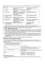
(7) [BFM #29] Error status: When an error occurs, use the FROM command to read out the details of the (8)[BFM #30]The identification code for a special block is read using the FROM command.The identification code for the LX3V-4DA unit is K3020.The MPU can use this facility in the program to identify the special block before commencing any data transfer from and to the special block. • Values of BFM #0, #5, and #21, (marked E) are stored in EEPROM memory of the LX3V-4DA. BFM #10 to #17 are copied to EEPROM when the gain/offset setting command BFM #8, #9 is used. Also, BFM #20 causes resetting...
Open the catalog to page 5
(2) Set the MPU to STOP, and turn on the power. Write the above program then switch the MPU to RUN. (3) Analog values will be sent from DO (BFM #1), D1 (BFM #2), D2 (BFM #3), and D3 (BFM #4) to the respective output channels of the LX3V-4DA. When the MPU is in STOP, the analog values set before stopping the MPU will remain output. (The output will be held); (4) When the MPU is in STOP, the offset values can also be output. For a detailed description, refer to For the following program, CH1 and CH2 of the LX3V-4DA connected at special block position No. 1 are used as voltage output channels, CH3...
Open the catalog to page 6
[Example of preventive measure] Power switch analog unit The standard characteristics (factory default) are shown by the solid lines in the figure below. These characteristics can be adjusted according to the conditions of the user's system. Standard characteristics Standard characteristics of current Standard characteristics of current Digital input - Digital input ■Digital input • . . . Gain value : Analog output value when the digital input is +1,000 ▲ . . . Offset value : Analog output value when the digital input is 0 When the slope of the I/O characteristic line is steep: Slight changes...
Open the catalog to page 7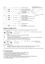
OPERATION START characteristics will be as follows mode of the output channel. . Sets the offset data. (Offset value: 7 mA) Sets the gain data. (Gain value: 20 mA) CH2 offset/gain setting command Inhibits adjustment of I/O characteristics Outline of FROM and TO commands: For a detailed description, refer to the FX Programming Manual. Read command : Special unit or block number (K0 to K7, numbered from the MPU) : Buffer memory head address (K0 to K31) : Head device number of destination data. T, C, D, KnM, KnY, KnS, V, and Z can be used to designate the head device. Each device number can be qualified...
Open the catalog to page 8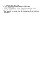
Off : Supply 24 VDC (+10%) to the LX3V-4DA. (4) Check the status of the D/A conversion indicator lamp (LED) of the LX3V-4DA. Flash: D/A conversion is normal. On or off : The ambient conditions are not suitable for the LX3V-4DA, or the LX3V-4DA is defective. (5) Check that the external load resistance connected to each analog output terminal does not exceed the capacity of the LX3V-4DA drive (voltage output: 2kΩ to 1 MΩ / current output: 500Ω ). (6) Check the output voltage or current value using a voltmeter or ammeter, and confirm that the output meets the I/O characteristics. If the output does...
Open the catalog to page 9All Wecon Technology Co.Ltd catalogs and technical brochures
 PRODUCTS CATALOG
24 Pages
 Servo Catalog
8 Pages
 WECON Inverter
4 Pages
 NDUSTRX APPL CAT ON MANUAL
6 Pages
 LX3VP
LX3VP4 Pages
 Wecon A8 Products Catalog
6 Pages
 WECON PLC Products Catalog
8 Pages
 LX3V-4PT Module
8 Pages
 LX3V-4AD Module
9 Pages
 WECON LEVI777E catalog
3 Pages
 WECON PLC Catalog
8 Pages
 Wecon Tablet PC
9 Pages
 Wecon Products
10 Pages
 Wecon Industrial Panel PC
23 Pages
 WECON PLC Module LX2N-4AD
9 Pages
 WECON HMI Install Manual
2 Pages
 Wecon LX series PLC
8 Pages
 Wecon CNS7-200 serise PLC
34 Pages


