- Catalogs
- WayCon Positionsmesstechnik GmbH
- Signal Conditioner PMX-24
- Company
- Products
- Catalogs
- News & Trends
- Exhibitions
Signal Conditioner PMX-24
1 /4Pages

Signal Conditioner PMX-24
1 /4Pages
Catalog excerpts
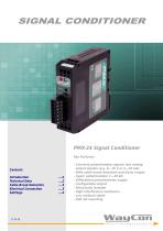
Content: Introduction Technical Data Cable Break Detection Electrical Connection Settings PMX-24 Signal Conditioner Key Features: - Converts potentiometer signals into analog output signals (e.g. 0...10 V or 4...20 mA) - With cable break detection and alarm output ...2 - Input: potentiometer 1...20 kfi . 2 - Differential potentiometer supply . 4 - High interference resistance - Low residual ripple - DIN rail mounting
Open the catalog to page 1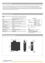
Signal conditioners are used for potentiometers to convert an input signal into a different proportional output signal. These are often standardised values such as 0...10 V or 4...20 mA, needed for ordinary connection to controls. A signal conditioning and an electrical isolation ensures an optimal signal performance. The PMX-24 offers various current and voltage outputs, e.g. 4...20 mA, 0...10 V, 0...5 V, ±5 V, ±10 V, which can be configured easily via DIP switch (switch on the board). The signal output is electrically isolated and characterised by extremely low residual noise, free of any spikes....
Open the catalog to page 2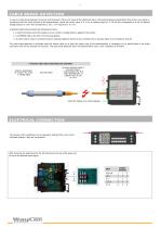
In case of a cable break between the sensor and transducer, there is no signal at the electronics input. Conventional devices would detect this as the cursor signal in accordance with the initial position of the potentiometer, where the cursor signal is 0 V. For an analog output of 4...20 mA this corresponds to 4 mA, for bipolar voltage outputs of ±10 V this corresponds to -10 V, ±5 V output thus -5 V, etc. A detected cable break activates the following functions: 1. A switch fully disconnects the outputs and no current or voltage signal is applied to the output. 2. A red ERROR LED on the front...
Open the catalog to page 3
SETTINGS Setting the Offset (zero) and gain: Please note, when using long lines between the potentiometer and conditioner the zero point and gain may change. Install the potentiometer with the required cable length and then set the zero point and gain. We recommend the following procedure: 1. Move the potentiometer to the start of the measuring range. 2. Offset: Adjust the front Zero potentiometer to 4.000 mA (for 4...20 mA) or 0.000 V (for 0...10 V) output signal. 3. Move the potentiometer to the end of the measuring range. 4. Set gain: Adjust the Gain potentiometer to 20.000 mA or 10.000 V...
Open the catalog to page 4All WayCon Positionsmesstechnik GmbH catalogs and technical brochures
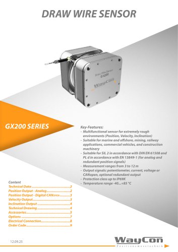 Draw wire sensor GX200
10 Pages
 LVIG SERIES
5 Pages
 LAS2-TM SERIES
3 Pages
 LASER SENSORS
8 Pages
 Linear potentiometers
4 Pages
 Magnetostrictive transducers
4 Pages
 Ultrasonic sensors
4 Pages
 Hydraulic sensors
4 Pages
 Product overview
12 Pages
 Capacitive Sensor KS
9 Pages
 LX Compact Sensor
6 Pages
 SX300 Hydraulic transducer
8 Pages
 Linear Potentiometer LMS18
4 Pages
 Linear Potentiometer LSW
4 Pages
 Linear Potentiometer LZW2-IP
4 Pages
 B36 Incremental Encoder
5 Pages
 SSI Absolute Encoder
9 Pages
 Profinet Absolute Encoder
6 Pages
 Laser Sensor LAS-T5
5 Pages
 Laser Sensor LAM
9 Pages
 Linear Potentiometer LZW
6 Pages
 Ultrasonic Sensors UFP, UPA
7 Pages
 CANopen Absolute Encoder
12 Pages
 Profibus Absolute Encoder
6 Pages
 EtherCAT Absolute Encoder
6 Pages
 Analog Rotary Sensor WP
8 Pages
 Draw wire sensor HX
10 Pages
 Long Distance Laser LLD-150
5 Pages
 Laser Sensor LAV
5 Pages
 Linear Potentiometer LZW2
4 Pages
 Linear Potentiometer LZW1
4 Pages
 Linear Potentiometer LRW1
4 Pages
 Analog Absolute Encoder M36
7 Pages
 Laser sensors LAR
4 Pages
 Draw Wire Sensor SX50
13 Pages
 Draw Wire Sensor SX80
14 Pages
 Draw Wire Sensor SX120
14 Pages
 Linear Potentiometer LRW
5 Pages
 Hydraulic Transducer SX200
6 Pages
 Digital Length Gauges
5 Pages
 Digital Scale DMO
3 Pages
 Draw Wire Sensor MH120
11 Pages
 Draw Wire Sensors MH60
9 Pages
 Draw Wire Sensor FX-HM
4 Pages
 Draw Wire Sensor ZX
3 Pages
 Laser Sensor LAH-G1
4 Pages
 VTS-Box Teach Electronic
3 Pages
 Analog Magnetic Scales MXAZ
4 Pages
 Digital Magnetic Scale MXS2
4 Pages
 SSI Absolut Encoder F36
7 Pages
 Analog Absolut Encoder M58
5 Pages
 Draw wire sensors
8 Pages


- Display module
- Angular encoder
- Industrial display panel
- Incremental encoder
- Proximity switch
- Incremental rotary encoder
- Digital indicator
- Touch screen display panel
- Cylindrical proximity sensor
- Absolute rotary encoder
- LED display panel
- Panel panel meter
- Position transducer
- Solid-shaft rotary encoder
- Optical rotary encoder
- Hollow-shaft rotary encoder
- Linear position transmitter
- Magnetic rotary encoder
- Industrial rotary encoder
- Displacement transducer