- Catalogs
- WayCon Positionsmesstechnik GmbH
- Linear Potentiometer LZW
- Company
- Products
- Catalogs
- News & Trends
- Exhibitions
Linear Potentiometer LZW
1 /6Pages

Linear Potentiometer LZW
1 /6Pages
Catalog excerpts
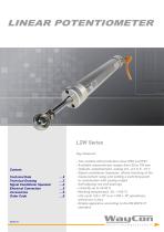
Key-Features: - Two models with protection class IP65 and IP67 - Available measurement ranges from 50 to 750 mm - Outputs: potentiometer, analog 0.5...4.5 V, 0...10 V - Signal conditioner Squeezer: allows teaching of the measurement range and setting a switching point in combination with analog output - Self-aligning rod end bearings - Linearity up to ±0.05 % - Working temperature -30...+100 °C - Life cycle >25 x 106 m or >100 x 106 operations, whichever is less - Simple apparatus according to the EN 60079-11 standard
Open the catalog to page 1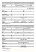
TECHNICAL DATA LZW-M /-B / -IP, POTENTIOMETER OUTPUT Model Measurement range * Protection class Displacement speed Resolution Repeatability Resolution depends on the signal quality of the ref erence v oltage respectiv ely supply v oltage. [mm] Recommended cursor current Maximum cursor current Maximum applicable v oltage Temperature coef f icient of resistance Temperature coef f icient of output v oltage Electrical isolation Dielectric strength Working temperature Storage temperature -30...+100 -50...+100 >25 x 106 m or >100 x 106 operations (whichev er is less) Stainless steel, AISI 303 Housing...
Open the catalog to page 2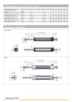
DIMENSIONS AND ELECTRICAL DATA Usef ul electrical stroke (B) +3/-0 Theoretical electrical stroke (C) ±1 Mechanical stroke (D) LZW-M, LZW-B Mechanical stroke (D) LZW-IP Housing length (E) LZW-M, LZW-B Housing length (E) LZW-IP Minimum distance (A) LZW-M, LZW-B Minimum distance (A) LZW-IP TECHNICAL DRAWING LZW-M / LZW-B
Open the catalog to page 3
LZW-M sensors with the analog output versions 5VT and 10VT are equipped with a teachable, internal electronics, called VT-Electronics. The signals provided by the sensor’s potentiometer are digitized by the VT-Electronics. This digital information is first processed by the electronics, then transformed back and given out as an analog output signal 0 to 10 V or 0.4 to 4.5 V. The digitization offers two possibilities of adjustment, by which the sensor can be configured individually using the Squeezer: 1) Teaching of the measurement range. After a successful teaching process the Squeezer can be...
Open the catalog to page 4
Electrical connection Installation instructions • Please pay attention that the sensor is not used as a variable resistor. • Please be careful while calibrating the sensor to set the stroke so that the output signal does not drop below 1 % or exceed 99 % of the supply voltage. ACCESSORIESOutput LZW-IP (IP67)Output LZW-B (IP65) Output LZW-M (IP65) Cable with connector M12, 4 poles, shielded CON011: mating connector for self assembly IP40, 5 pole, cable diameter 4...6 mm CON008: mating connector, angular for self assembly IP40, 4 pole, PG9 cable gland, cable 0 6...8 mm Squeezer Controller for LZW-M-...-4,5VT...
Open the catalog to page 5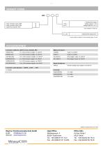
Subject to change without prior notice WayCon Positionsmesstechnik GmbH email: [email protected] internet: www.waycon.biz WauLnn Posilionsmcsslcchn ik
Open the catalog to page 6All WayCon Positionsmesstechnik GmbH catalogs and technical brochures
 Draw wire sensor GX200
10 Pages
 LVIG SERIES
5 Pages
 LAS2-TM SERIES
3 Pages
 LASER SENSORS
8 Pages
 Linear potentiometers
4 Pages
 Magnetostrictive transducers
4 Pages
 Ultrasonic sensors
4 Pages
 Hydraulic sensors
4 Pages
 Product overview
12 Pages
 Capacitive Sensor KS
9 Pages
 LX Compact Sensor
6 Pages
 SX300 Hydraulic transducer
8 Pages
 Linear Potentiometer LMS18
4 Pages
 Linear Potentiometer LSW
4 Pages
 Linear Potentiometer LZW2-IP
4 Pages
 B36 Incremental Encoder
5 Pages
 SSI Absolute Encoder
9 Pages
 Profinet Absolute Encoder
6 Pages
 Laser Sensor LAS-T5
5 Pages
 Laser Sensor LAM
9 Pages
 Ultrasonic Sensors UFP, UPA
7 Pages
 CANopen Absolute Encoder
12 Pages
 Profibus Absolute Encoder
6 Pages
 EtherCAT Absolute Encoder
6 Pages
 Analog Rotary Sensor WP
8 Pages
 Draw wire sensor HX
10 Pages
 Long Distance Laser LLD-150
5 Pages
 Laser Sensor LAV
5 Pages
 Linear Potentiometer LZW2
4 Pages
 Linear Potentiometer LZW1
4 Pages
 Linear Potentiometer LRW1
4 Pages
 Analog Absolute Encoder M36
7 Pages
 Laser sensors LAR
4 Pages
 Draw Wire Sensor SX50
13 Pages
 Draw Wire Sensor SX80
14 Pages
 Draw Wire Sensor SX120
14 Pages
 Linear Potentiometer LRW
5 Pages
 Hydraulic Transducer SX200
6 Pages
 Digital Length Gauges
5 Pages
 Digital Scale DMO
3 Pages
 Draw Wire Sensor MH120
11 Pages
 Draw Wire Sensors MH60
9 Pages
 Draw Wire Sensor FX-HM
4 Pages
 Draw Wire Sensor ZX
3 Pages
 Laser Sensor LAH-G1
4 Pages
 VTS-Box Teach Electronic
3 Pages
 Analog Magnetic Scales MXAZ
4 Pages
 Digital Magnetic Scale MXS2
4 Pages
 SSI Absolut Encoder F36
7 Pages
 Signal Conditioner PMX-24
4 Pages
 Analog Absolut Encoder M58
5 Pages
 Draw wire sensors
8 Pages


- Display module
- Angular encoder
- Industrial display panel
- Incremental encoder
- Proximity switch
- Incremental rotary encoder
- Digital indicator
- Touch screen display panel
- Cylindrical proximity sensor
- Absolute rotary encoder
- LED display panel
- Panel panel meter
- Position transducer
- Solid-shaft rotary encoder
- Optical rotary encoder
- Hollow-shaft rotary encoder
- Linear position transmitter
- Magnetic rotary encoder
- Industrial rotary encoder
- Displacement transducer