- Catalogs
- Watz Hydraulik GmbH
- Cylinder ZI
Cylinder ZI
1 /10Pages

Cylinder ZI
1 /10Pages
Catalog excerpts

Zylinder ZI nach ISO 6020 (160 bar) Cylinder ZI according to ISO 6020 (160 bar) Doppeltwirkender Zylinder Double Acting Cylinder
Open the catalog to page 1
Typenschlüssel Model Code Z I A - 100 / 70 - 250 - MP5 - DB - A - GK 63 1 ZI = Normzylinder ZIGL = Gleichlaufnormzylinder (auf Anfrage) ZI = Standardized cylinder ZIGL Double rod cylinder (on request) = 2 Piston rod end I = Internal thread A = External thread 3 Kolben-Ø (in mm, siehe Tabelle) 4 Kolbenstangen-Ø (in mm, siehe Tabelle) 6 Zylinderbefestigung MX5 = Kopfbohrung MX6 = Bodenbohrung MS2 = Fußbefestigung MP5 = Gelenklager am Boden MP1 = Gabelkopf Rechteckflansch ME5 = vorne ME6 = hinten Schwenkzapfen MT1 = vorne MT2 = hinten MT4 = mitte (Rohr) Zugankerverlängerung MX1 = vorne und hinten...
Open the catalog to page 2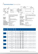
Technische Daten Technical Data Normen: The cylinder installation and mounting types conform to the ISO 6020 DIN 24554 standards Nominal pressure: 160 bar Proof pressure: 240 bar Stroke length: to 3.000 mm (the permissible stroke is dependable of the buckling) Installation position: arbitrary Hydraulic fluid: Mineral oils DIN 51524 (HL, HPL) Fluid temperature range: -20 to + 80° C Viscosity range: 2,8 to 380 mm/s Stroke velocity: 0,5 m/s Stroke length tolerance: Piston-Ø up to 63: + 1,5 mm Piston-Ø from 80: + 2 mm Normen: Die Einbaumaße und Befestigungsarten der Zylinder entsprechen der geltenden...
Open the catalog to page 3
Zylinderbefestigungen Cylinder Mounting Types MP1 Gabelkopf Fork clevis Kolben-Ø D Piston-Ø D MP5 Gelenklager Self-aligning clevis ME5 Recheckflansch vorne Flange front MT1 Schwenkzapfen vorne Trunnion mounting front Andere Zylinderbefestigungen auf Anfrage. Further cylinder mounting types on req
Open the catalog to page 4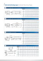
Zylinderbefestigungen Cylinder Mounting Types MT2 Schwenkzapfen hinten Trunnion mounting rear Kolben-Ø D Piston-Ø D MT4 Schwenkzapfen mitte Trunnion mounting middle MS2 Fußbefestigung Foot mounting MX1 Zugankerverlängerung vorne/hinten Tie rod extension front/rear Kolben-Ø D Piston-Ø D
Open the catalog to page 5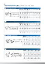
Zylinderbefestigungen Cylinder Mounting Types MX3 Zugankerverlängerung vorne Tie rod extension front Kolben-Ø D Piston-Ø D MX2 Zugankerverlängerung hinten Tie rod extension rear Kolben-Ø D Piston-Ø D MX5 Kopfbohrung Front tapped holes Kolben-Ø D Piston-Ø D MT1 Bodenbohrung Rear tapped holes Kolben-Ø D Piston-Ø D
Open the catalog to page 6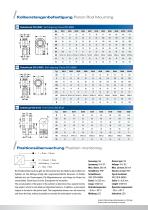
Kolbenstangenbefestigung Piston Rod Mounting GK Gelenkkopf ISO 6982 Self-aligning Clevis ISO 6982 Typ GD Gelenkkopf ISO 24555 Self-aligning Clevis ISO 24555 Typ GU Gabelkopf ISO 8132 Fork Clevis ISO 8132 Typ Positionsüberwachung Position monitoring Die Positionsüberwachung gibt die Information über die Stellung des Kolbens im Zylinder am. Die Abfrage erfolgt über magnetempfindliche Sensoren. Im Kolben befindet sich ein Dauermagnet. Die Magnetsensoren sind längs der Nuten frei verschiebbar. Damit lässt sich der Schaltpunkt frei einstellen. The actual position of the piston in the cylinder is determined...
Open the catalog to page 7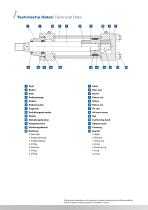
Technische Daten Technical Data 7 a. Abstreifer b. Stangendichtung c. Kolbendichtung d. O-Ring e. Stützring f. O-Ring g. O-Ring a. Wiper b. Rod seal c. Piston seal d. 0-ring e. Back-up ring f. 0-ring g. 0-ring Zylinder deren Einsatzdaten von den genannten Parametern abweichen sind auf Anfrage erhältlich. Cylinders outside the above parameters are available on request
Open the catalog to page 8
Ermittlung der zulässigen Knickbelastung FK zul Kolbenstangen mit einer verhältnismäßig großen Baulänge gegenüber ihrem Durchmesser müssen auf Knickung berechnet werden. Wird die zulässige Knickbelastung überschritten, besteht die Gefahr, dass die Kolbenstange sich plastisch verformt. Die Berechnung der Knickbelastung basiert auf der Länge des Zylinders im ausgefahrenen Zustand in Abhängigkeit zur jeweiligen Befestigungsart im senkrechten Einbaufall. dK = Kolbenstangendurchmesser [mm] S = Sicherheitsfaktor in der Regel 2- 5 [üblicherweise Faktor 3] SK = freie Knicklänge, sie setzt sich aus dem...
Open the catalog to page 9
Watz Hydraulik GmbH Auweg 8 | 35457 Lollar | Germany Die angegebenen Daten dienen nur zur Produktbeschreibung und sind nicht als zugesicherte Eigenschaft im Rechtssinne zu verstehen. The specified data is for product description only and must not be interpreted as warranted characteristics in a legal sence. Tel.: + 49 6406 9102-0 Fax: + 49 6406 9102-41 E-Mail: info@ watzhydraulik.de www.watzhydraulik.de
Open the catalog to page 10All Watz Hydraulik GmbH catalogs and technical brochures
 WATZ HYDRAULIK
16 Pages
 Block cylinder 500 bar
8 Pages
 Plunger cylinder ZE 300 bar
6 Pages
 Round cylinder ZM 250 bar
10 Pages
 Round cylinder ZD 160 bar
8 Pages

- Test stand
- Double-acting cylinder
- Hydraulic cylinder
- Automated test bench
- Single-acting cylinder
- BIO-UV compact cylinder
- BIO-UV industrial cylinder
- Standard cylinder
- ISO cylinder
- Industrial test bench
- Pressure test bench
- Hydraulic test bench
- Valve test bench
- Cylinder with piston rod
- Tie-rod cylinder
- Briquetting press
- Compact test station
- Round cylinder
- Chip briquette press